
User Manual


Atmel AT03911: REB233CBB Module – User Manual [APPLICATION NOTE]
42156BWIRELESS02/2014
5
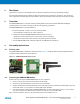
5.2 Radio PCB
The Radio PCB carries the radio transceiver AT86RF233 [3]. The radio transceiver is a high performance RF-CMOS
2.4GHz radio transceiver targeted for IEEE802.15.4, ZigBee, RF4CE, 6LoWPAN, and ISM applications. The
identification EEPROM carries Radio PCB information used by the Microcontroller PCB.
5.3 Antennas
The antennas intended for the REB233CBB Module, see B.3 and [2], are to be connected to the SMA connectors on the
Radio PCB. A proper antenna orientation can enhance the radio link budget. Especially an orthogonal orientation
between the two antennas, see Figure 6-1, decreases the probability of RF signal extinction.
5.4 Microcontroller PCB
The Microcontroller PCB carries the ATxmega256A3 MCU [4]. The MCU is a high-performance, low-power 8/16-bit
Atmel
AVR
®
XMEGA
®
MCU with 256KB in-system, self-programmable flash, 8KB boot code section with independent
lock bits, 16KB internal SRAM and 4KB EEPROM.
5.5 Power Supply
The REB233CBB Module is powered by two AAA batteries. The power switch disconnects batteries from the entire
board. External power is not routed through the power switch.
Note: There is no protection against over-voltage.
5.6 LEDs and buttons
For simple applications, and to provide status information, a user interface is provided on-board, consisting of three
LEDs and two pushbuttons
The LEDs (D1…D3) are connected to PB0..2 for active-high operation, whereas the pushbutton (T1) pulls PB3 to GND.
The second pushbutton (RESET) is connected to the MCUs reset pin.
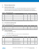
Table 5-1. LED/Button connection
ATxmega256A3
I/O
ATxmega256A3
I/O
PB0 (6)
D1
PB3 (9)
T1
PB1 (7)
D2
RESET
T2
PB2 (8)
D3
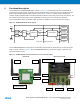
5.7 UART/USART
The signal lines for asynchronous serial operation of the Atmel ATxmega256A3 (USARTD0) are connected to header
USARTD0. In addition, the MCU reset line is connected to pin 5 of this header. This can be used to work with a serial boot
loader. No level conversion is done; therefore, an external RS232/TTL conversion circuit is required.
The header pin-out mates with the available RS232/TTL converter in Figure 5-3.
Table 5-2. Connection of USARTD0
ATxmega256A3
Header USARTD0
Description
PD2 (28)
RxD (4)
Asynchronous serial in
PD3 (29)
TxD (1)
Asynchronous serial out