
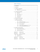
User Manual


Atmel AT03911: REB233CBB Module – User Manual [APPLICATION NOTE]
42156BWIRELESS02/2014
3
2. Disclaimer
Typical values contained in this application note are based on simulations and testing of individual examples.
Any information about third-party materials or parts was included in this document for convenience. The vendor may
have changed the information that has been published. Check the individual vendor information for the latest changes.
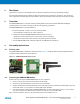
3. Overview
The REB233CBB Module is a compact solution providing wireless connectivity between IEEE 802.15.4/ZigBee
compliant devices. The module is compliant to EU and US regulatory requirements.
The REB233CBB Module is an ideal platform to:
Become familiar with a ready-to-use radio product by Atmel
No configuration required for out-of-box experience
Evaluate the outstanding REB233CBB Module performance, such as
Excellent receiver sensitivity achieved at ultra-low current consumption
Performance improvements and robustness by operating antenna diversity
Test the REB233CBB Module hardware support of the IEEE 802.15.4 standard [1]
4. Assembly instructions
4.1 Delivery state
The REB233CBB Module is delivered in dismounted state. Figure 4-1 shows the Microcontroller PCB with batteries
inserted, the Radio PCB and two swivel antennas.
Figure 4-1. REB233CBB Module delivery state
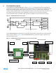
4.2 Preparing the REB233CBB Module
Follow these steps to setup the REB233CBB Module for correct operation:
1. Check or set the power switch off at the Microcontroller PCB.
2. Insert the two delivered batteries and check for correct polarization.
3. The RF-Shielding of the Radio PCB must be faced to the battery holder of the Microcontroller PCB. Plug in the
Radio PCB header ‘X1’ into the Microcontroller PCB socket ‘Expand 1’.
4. The swivel antennas provided with the REB233CBB Module are tested and approved (see B.3). One antenna
must be mounted on each SMA coaxial connector ‘X2’ and ‘X3’ port of the Radio PCB.
Note, to ensure compliance, the use of any other antenna type is not permitted, see B.3.