
User's Manual


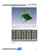


Table Of Contents
- 1 Introduction
- 2 Disclaimer
- 3 Overview
- 4 Functional description
- 5 PCB layout description
- 6 Mechanical description
- 7 Electrical characteristics
- 8 Abbreviations
- References
- EVALUATION BOARD/KIT IMPORTANT NOTICE
- 9 Table of contents

Atmel AVR2092
27
8427A-AVR-10/11
Figure 5-20. Some main radiation directions with polarization angle, seen from the
PCB bottom side.
There is one radiation direction where no diversity effect exists. The direction is A=0,
F=180 and P=0. For that case both antennas have a polarization that is turned by
180deg against each other. However, it is still horizontal and the antenna gain is
similar for both antennas.
Table 5-1. Measured radiation power for different radiation directions.
Antenna Azimuth (A) Phi (F) Polarization (P) dBm EIRP
A1 -60 135 45 4
A2 -15 25 -30 5.8
A1 0 180 0 5.9
A2 0 180 0 6.6
A1 70 55 -70 7
A1 105 180 0 3.7
A2 110 85 65 4.3
A1 110 -90 45 4.5
A2 110 -90 -45 5.5
According to the manufacturer datasheet, the antenna has a typical average gain of
1dBi with a peak gain of 3dBi. Considering the fact that the RF232 provides 3dBm of
transmitting power after the balun, these measurements prove the maximum TX
performance.