
User's Manual


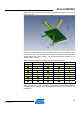


Table Of Contents
- 1 Introduction
- 2 Disclaimer
- 3 Overview
- 4 Functional description
- 5 PCB layout description
- 6 Mechanical description
- 7 Electrical characteristics
- 8 Abbreviations
- References
- EVALUATION BOARD/KIT IMPORTANT NOTICE
- 9 Table of contents

Atmel AVR2092
25
8427A-AVR-10/11
multipath environments. The dual antenna setup has access to many more
propagation modes than a single antenna.
By switching from one antenna to the other, the physical antenna location is changing
because of the antenna distance and on top of that the wave polarization is changing
as well. The achieved propagation path effect of this switch was already illustrated in
Figure 5-10, page 19.
Figure 5
-17. Radiated measurement for Azimut -50deg, Phi -35deg, Polarization
65deg.
The measurement setup inside of an anechoic chamber is shown in Figure 5-17. A
measurement
position is characterized by three angels. There is the azimuth angle,
where the whole test device carrier is turning around a vertical axis. The turning angle
of the test board around a horizontal axis is called Phi. In Addition the receive
antenna can be turned to adjust the polarization angle.
The following 3D models show the board and the radiation properties for some of the
main radiation directions. The cylinders point into the measured radiation direction,
the arrows at the end of each pointer indicate the wave polarization direction.
The yellow pointers belong to antenna A1 while the green pointers indicate radiations
from A2. Please refer to Figure 5-1 fo
r the antenna reference markers A1 and A2 or
have a look at the physical board.