
User's Manual


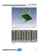


Table Of Contents
- 1 Introduction
- 2 Disclaimer
- 3 Overview
- 4 Functional description
- 5 PCB layout description
- 6 Mechanical description
- 7 Electrical characteristics
- 8 Abbreviations
- References
- EVALUATION BOARD/KIT IMPORTANT NOTICE
- 9 Table of contents

24
Atmel AVR2092
8427A-AVR-10/11
Figure 5-15, page 23, and Figure 5-16 show the final result as a diagram and on the
board.
Figure 5-16. Antenna tuning with series and shunt capacitor.
In most cases, it is beneficial to tune the antenna a little towards higher frequencies.
The reason is that environmental changes in most cases tune the antenna down to
lower frequencies. Such environmental changes can be any kind of object that is
situated near the antenna, such as a housing or table surface.
The tuning determined in this example is only valid for the antenna example board.
The REB232ED, with its different ground plane design and many more differences,
may have other parts assembled.
5.7.4 Final board antenna radiation pattern
The a
ctual radiation pattern for the final board is rather complicated and very difficult
to describe. Traditional radiation diagrams where the device under test is turned in all
three axes and the received power for a vertical and a horizontal antenna are shown
in a polar diagram do not provide a correct picture. Due to the antenna placement in a
45deg angle, the polarization changes dramatically for such a turn. To see the full RF
power the RX Antenna would require maintaining the correct polarization angel for
such a measurement.
No matter what problems this setup creates when measuring the radiated power,
such a radiation pattern is exactly what is required to reduce fading effects in indoor