
User's Manual

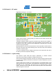


Table Of Contents
- 1 Introduction
- 2 Disclaimer
- 3 Overview
- 4 Functional description
- 5 PCB layout description
- 6 Mechanical description
- 7 Electrical characteristics
- 8 Abbreviations
- References
- EVALUATION BOARD/KIT IMPORTANT NOTICE
- 9 Table of contents

Atmel AVR2092
17
8427A-AVR-10/11
Because the antenna has to operate in an environment different from that of the
manufacturer’s evaluation board, the correct frequency tuning has to be verified. The
antenna distance, required for optimum diversity operation, provides enough board
space to use a low-cost tuning method based on a transmission line and capacitors.
The actual tuning procedure is explained in Section 5.7.3, page 20.
Figure 5-8. Initial antenn
a tuning and test board.
Besides the antenna tuning, the test board was used to measure the diversity effect
and the coupling between the two antennas. The better the two antennas are isolated
from each other, the higher is the diversity advantage for the receiver.
It has to be considered that the unused antenna is operating against an open line end
because the RF switch, U1, has high impedance in the off position. A low coupling in
between the antennas is therefore required.
Direct coupling measurement results between both antennas are shown in Figure 5-9,
page 18. Ove
r the operating frequency range, the antenna separation is >15dB. That
is achieved mainly with the ±45-degree installation. The 90-degree turn between left
and right antennas causes orthogonal radiation patterns and minimal coupling.
Because the polarization of a received wave is not deterministic in a multipath
environment, this setup is also capable of selecting the optimum polarization match
for an incoming wave.
The other design aspect is the antenna distance. The antenna distance has to be
large enough to ensure only one of the two antennas is present in a local fading
minimum. Figure 5-10, p
age 19, shows the field strength plot for both antennas,
dependent on the board position. For this test, the antenna board was moved along a
workbench using a stepper motor. The transmitter was positioned several meters
away on another workbench. No direct line of sight connection is ensured using a