
User's Manual


Atmel AVR2042
9
8334A-AVR-05/11
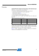
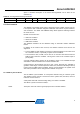
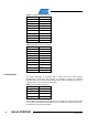
Figure 5-4. User I/Os.
PB2
PB1
PB0
PB3
The LEDs are connected to PB0..2 for active-high operation. The key will pull PB3 to
GND. The key is intended to be used in combination with the internal pull-up resistor.
Table 5-5. LED/Button connection.
ATxmega256A3
I/O
PB0 (6)
D1
PB1 (7)
D2
PB2 (8)
D3
PB3 (9)
T1
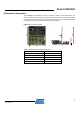
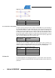
To get full accessibility to all I/O pins of the Atmel ATxmega256A3, three 8-bit ports
are routed to 10-pin headers. Each header provides additional pins for VTG and
GND. Figure 5-5 shows the pin-out for a single port.
Figure 5-5. General pin-out of I/O port headers.
Table 5-6. PORTA header connection.
Header PORTA
ATxmega256A3
1
PA0 (62)
2
PA1 (63)
3
PA2 (64)
4
PA3 (1)
5
PA4 (2)
6
PA5 (3)
7
PA6 (4)
8
PA7 (5)
9
GND
10
VTG