
User's Manual
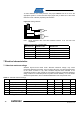
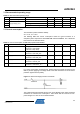
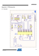
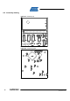
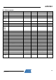
Table Of Contents

AVR2042
11
8334A-AVR-11/10
7.2 Recommended operating range
Table 7-2. Recommended operating range.
No. Parameter Condition Minimum Typical Maximum Units
7.2.1 Temperature range -10 +60 °C
7.2.2 Plain REB-CBB 1.6 3.0 3.6 V
7.2.3 REB plugged on REB-CBB 1.8 3.0 3.6 V
7.2.4
Supply voltage (Vcc)
Serial flash access in usage 2.3 3.0 3.6 V
7.3 Current consumption
Test conditions (unless otherwise stated):
V
DD
= 3.0V, T
OP
= 25°C
The following table lists current consumption values for typical scenarios of a
complete system composed of Atmel REB-CBB and Atmel REB231. The z-diode has
been removed as described above.
Table 7-3. Current consumption of REB-CBB populated with REB231.
No. Parameter Condition Minimum Typical Maximum Units
7.3.1 Supply current
MCU @ power-down,
transceiver in state SLEEP,
serial flash in Deep-Sleep
17 µA
7.3.2 Supply current MCU @ 2MHz,
transceiver in state TRX_OFF
3 mA
7.3.3 Supply current MCU @ 16MHz (int. RC 32MHz),
transceiver in state TRX_OFF
15 mA
7.3.4 Supply current MCU @ 16MHz (int. RC 32MHz),
transceiver in state RX_ON
28 mA
7.3.5 Supply current MCU @ 16MHz (int. RC 32MHz),
transceiver in state BUSY_TX
26 mA
For current consumption measurements, please regard the z-diode mounted on the
REB. It prevents applying overvoltage stress to the radio transceiver circuit as well as
protection against reverse polarity.
Figure 7-1. REB overvoltage protection mechanism.
The z-diode draws approximately 6mA at 3.0V (type: BZG05-C3V9), which should be
considered in overall current consumption. The z-diode shall be removed for low-
power designs or in case of current measurements.