
User's Manual
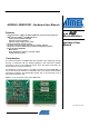
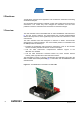
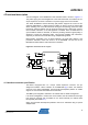
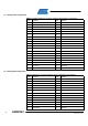
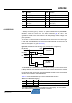
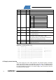
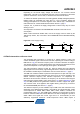
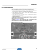
Table Of Contents

AVR2043
3
8345A-AVR-11/10
4 Functional description
The block diagram of the REB231ED radio extender board is shown in Figure 4-1.
The power supply pins and all digital I/Os of the radio transceiver are routed to the 2 x
20-pin expansion connector to interface to a power supply and a microcontroller.
The Atmel AT86RF231 antenna diversity (AD) feature supports the control of two
antennas (ANT0/ANT1). A digital control pin (DIG1) is used to control an external RF
switch selecting one of the two antennas. During the RX listening period, the radio
transceiver switches between the two antennas autonomously, without the need for
microcontroller interaction, if the AD algorithm is enabled. Once an IEEE 802.15.4
synchronization header is detected, an antenna providing sufficient signal quality is
selected to receive the remaining frame. This ensures reliability and robustness,
especially in harsh environments with strong multipath fading effects.
Board-specific information such as board identifier, the node MAC address, and
production calibration values are stored in an ID EEPROM. The SPI bus of the
EEPROM is shared with the radio transceiver’s interface.
Figure 4-1. REB231ED block diagram.
4.1 Interface connector specification
The REB is equipped with a 2 x 20-pin, 100mil expansion connector. The pin
assignment enables a direct interface to the REB-CBB [2]. Further, the i
nterface
connects to the Atmel STK500/501 microcontroller development platform to enable
support for various Atmel 8-bit AVR
®
microcontrollers.
The REB is preconfigured to interface to an STK501 with an Atmel ATmega1281.
If an Atmel ATmega644 is used as the microcontroller, the 0 resistors R10 through
R18 must be removed and re-installed on the board manually as resistors R20
through R28 (see Exhibit A.1).
Other mi
crocontroller development platforms need to be interfaced using a special
adapter board.