
User's Manual
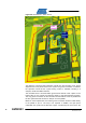
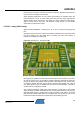
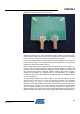
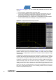
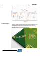
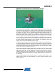
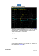
Table Of Contents

AVR2043
15
8345A-AVR-11/10
Figure 5-6. Initial antenna tuning and test board.
Besides the antenna tuning, the test board was used to measure the diversity effect
and the coupling between the two antennas. The better the two antennas are isolated
from each other, the higher is the diversity advantage for the receiver.
It has to be considered that the unused antenna is operating against an open line end
because the RF switch, U1, has high impedance in the off position. A low coupling in
between the antennas is therefore required.
Direct coupling measurement results between both antennas are shown in Figure 5-7,
page 16. Ove
r the operating frequency range, the antenna separation is >15dB. That
is achieved mainly with the ±45-degree installation. The 90-degree turn between left
and right antennas causes orthogonal radiation patterns and minimal coupling.
Because the polarization of a received wave is not deterministic in a multipath
environment, this setup is also capable of selecting the optimum polarization match
for an incoming wave.
The other design aspect is the antenna distance. The antenna distance has to be
large enough to ensure only one of the two antennas is present in a local fading
minimum. Figure 5-8, pa
ge 17, shows the field strength plot for both antennas,
dependent on the board position. For this test, the antenna board was moved along a
workbench using a stepper motor. The transmitter was positioned several meters
away on another workbench. No direct line of sight connection is ensured using a
large metal plate. The graph shows receive signal strength variations caused by the
interference of reflected waves reaching the receiver via different propagation paths.