
User's Manual
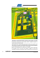
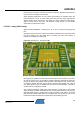
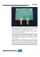
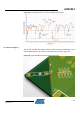
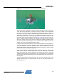
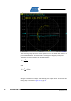
Table Of Contents

12
AVR2043
8345A-AVR-11/10
Figure 5-4. Board layout – XTAL section.
The reference crystal and load capacitors C34/35 form the resonator circuit. These
capacitors are to be placed close to the crystal. The ground connection in between
the capacitors should be the crystal housing contact, if available, resulting in a
compact, robust and stable resonator.
The resonator block is enclosed within ground traces around it and a plane on the
bottom side. Do not connect the resonator directly to the plane beneath the block.
The only ground connection for the resonator block should be a trace in parallel with
the two crystal lines that connects to TRX pin 27 or the paddle.
Based on recent experiments, the bottom ground connection shall be routed directly
to the paddle or pin 27. The loop is not required. In addition, the open space
underneath the crystal can be filled with copper. A small keep out trace next to the