
Data Sheet


r 0.1
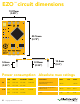
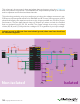
This schematic shows exactly how we isolate data and power using the ADM3260
and a few passive components. The ADM3260 can output isolated power up to 150 mW
and incorporates two bidirectional data channels.
This technology works by using tiny transformers to induce the voltage across an air gap.
PCB layout requires special attention for EMI/EMC and RF Control, having proper ground
planes and keeping the capacitors as close to the chip as possible are crucial for proper
performance. The two data channels have a 4.7kΩ pull up resistor on both the isolated
and non-isolated lines (R1, R2, R3, and R4) The output voltage is set using a voltage
divider (R5, R6, and R,7) this produces a voltage of 3.7V regardless of your input voltage.
Isolated ground is different from non-isolated ground, these two lines should not
be connected together.
C4
10uF
C1
0.1uf
VDDP
ADM3260
HDR_BTM
ISO-VCC
ISO-VCC
ISO-VCC
ISO-VCC
ISO-VCC
R5 R7
R4
R3
1.5K
R6
1.5K
C3
C2
C6
C5
10uF
10uF
0.1uF
0.1uF
1.5K
4.7K
4.7K
VDDISO
VISO
VSEL
NCNC
SCL1
SDA1
SCL2
SDA2
VIN
GNDP
GNDISO
GNDISO
GNDISO
GNDISO
GNDP
GNDP
GNDP
PDIS
VCC
VCC
VCC
VCC
VCC
RX/SCL
TX/SDA
NC
GND
ISO-GND
ISO-GND
GND
GND
R2 R14.7K 4.7K
HDR_TOP
VCC
RX/SCL
TX/SDA
NC
GND
Non-isolated Isolated
10 Copyright © Atlas Scientic LLC