V 4.1 Revised 12/19/17 Dissolved Oxygen ™ EZO Circuit Reads Dissolved Oxygen Range 0.01 − 100+ mg/L 0.1 − 400+ % saturation Accuracy +/– 0.05 mg/L Max rate 1 reading per sec Supported probes Any galvanic probe Calibration Temperature, salinity and pressure compensation Data protocol 1 or 2 point Yes UART & I2C Default I2C address 97 (0x61) Operating voltage 3.
This is sensitive electronic equipment. Get this device working in a solderless breadboard first. Once this device has been soldered it is no longer covered by our warranty. This device has been designed to be soldered and can be soldered at any time. Once that decision has been made, Atlas Scientific no longer assumes responsibility for the device’s continued operation. The embedded systems engineer is now the responsible party.
Table of contents Circuit dimensions Power consumption Absolute max ratings EZO TM circuit identification Operating principle 4 4 4 5 6 UART UART mode Default state Receiving data from device Sending commands to device LED color definition UART quick command page LED control Find Continuous reading mode Single reading mode Calibration Export/import calibration Temperature compensation Salinity compensation Pressure compensation Enable/disable parameters Naming device Device information Response codes Read
EZO circuit dimensions TM 13.97mm (0.55”) 20.16mm (0.79”) 5.8mm (0.22”) 8.38mm (0.32”) 10.8mm (0.4”) Power consumption Absolute max ratings 5V 3.3V 4 LED MAX STANDBY SLEEP Parameter MIN ON 13.5 mA 13.1 mA 0.66 mA -65 °C OFF 12.7 mA 12.7 mA Storage temperature (EZO™ D.O.) Operational temperature (EZO™ D.O.) -40 °C 25 °C 85 °C VCC 3.3V 5V 5.5V ON 12.1 mA 12 mA OFF 11.9 mA 11.9 mA 0.3 mA TYP MAX 125 °C Copyright © Atlas Scientific LLC r 0.
EZO circuit identification TM 6.0 EZO™ Dissolved Oxygen circuit Legacy Dissolved Oxygen circuit Viewing correct datasheet Viewing incorrect datasheet Click here to view legacy datasheet 5 Copyright © Atlas Scientific LLC r 0.
Operating principle The Atlas Scientific™ EZO™ Dissolved Oxygen circuit works with: Optical probe Slow response, requires external power, expensive. Polar Graphic probe Requires external power, output in μA. Galvanic probe Requires no external power, output in mV. A galvanic dissolved oxygen probe consists of a Polytetrafluoroethylene membrane, an anode bathed in an electrolyte and a cathode.
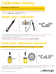
Calibration theory Calibrate first, compensate later. Temperature, salinity and pressure compensation values have no effect on calibration. The Atlas Scientific EZO™ Dissolved Oxygen circuit, has a flexible calibration protocol, allowing for single point or dual point calibration. Single point calibration A 1 5 10 15 20 25 30 B B C D E E F F G G H H I J 1 Do not unscrew A C D I 1 5 10 15 20 25 30 J 2 “Cal” 3 1. Pull off and discard cap from the Dissolved Oxygen probe.
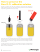
How to preserve the Zero D.O. calibration solution Oxygen is everywhere. The Zero D.O. calibration solution has been designed to chemically absorb oxygen. Once the bottle has been opened the test solution has been exposed to oxygen and will slowly stop working. Only the gas. (not the flame) N2 N2 Void space N2 N2 O2 O2 Gas Inside each bottle of the calibration solution is a small amount of nitrogen gas that helps displace oxygen out of the bottle during the filling process.
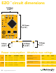
Power and data isolation The Atlas Scientific EZO™ Dissolved Oxygen circuit is a very sensitive device. This sensitivity is what gives the Dissolved Oxygen circuit its accuracy. This also means that the Dissolved Oxygen circuit is capable of reading micro-voltages that are bleeding into the water from unnatural sources such as pumps, solenoid valves or other probes/sensors.
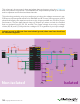
This schematic shows exactly how we isolate data and power using the ADM3260 and a few passive components. The ADM3260 can output isolated power up to 150 mW and incorporates two bidirectional data channels. This technology works by using tiny transformers to induce the voltage across an air gap. PCB layout requires special attention for EMI/EMC and RF Control, having proper ground planes and keeping the capacitors as close to the chip as possible are crucial for proper performance.
Correct wiring Bread board via USB Bread board 1 5 10 15 20 1 5 10 15 Carrier board 20 C C C RX D D D D TX E E E E F F F F G G G G H H H H I J 1 5 15 15 20 I I J J RX B C TX B GND A B VCC A B A A USB carrier board PWR Atlas Scientific TM I 1 5 15 15 20 J Part # COM-104 Part # ISCCB Part # USB-ISO Incorrect wiring Extended leads Sloppy setup A B C D E I 1 5 5 10 10 15 15 20 20 25 25 30 30 35 35 40 40 45 45 50 50 55
Available data protocols Default Unavailable data protocols SPI Analog RS-485 Mod Bus 4–20mA 12 Copyright © Atlas Scientific LLC r 0.
UART mode Settings that are retained if power is cut Baud rate Calibration Continuous mode Device name Enable/disable parameters Enable/disable response codes Hardware switch to I2C mode LED control Protocol lock Software switch to I2C mode Settings that are NOT retained if power is cut Find Pressure compensation Salinity compensation Sleep mode Temperature compensation r 0.
UART mode 8 data bits 1 stop bit Baud no parity no flow control 300 1,200 2,400 9,600 default 19,200 38,400 57,600 115,200 TX RX RX TX RX Data in TX TX RX Data out Vcc CPU 3.3V – 5.5V VCC 0V 0V Data format Reading Units Encoding Format Terminator 14 D.O.
Default state Mode UART Baud 9,600 Readings continuous Speed 1 reading per second Temperature compensation 20 °C Salinity compensation 0 (Fresh water) Pressure compensation 101.
Receiving data from device 2 parts ASCII data string Carriage return Command Terminator 9,600 baud (default) TX RX CPU 7.82 Receiver Sender Advanced ASCII: Hex: Dec: 16 7 . 8 2 37 2E 38 32 0D SDA SCL (TX) (RX) SDA SCL (TX) (RX) 55 46 56 50 13 SDA SCL (TX) (RX) SDA SCL (TX) (RX) SDA SCL (TX) (RX) Copyright © Atlas Scientific LLC r 0.
Sending commands to device 2 parts Command (not case sensitive) Carriage return ASCII data string Terminator TX RX CPU Sleep Sender Receiver Short Advanced ASCII: S l e e p Hex: 53 6C 65 65 70 0D Dec: 83 108 101 101 112 13 Short 17 Copyright © Atlas Scientific LLC r 0.
LED color definition Green Cyan Purple Red White UART standby Taking reading Changing baud rate Command not understood Find LED ON 5V +0.4 mA 3.3V +0.2 mA 18 Copyright © Atlas Scientific LLC r 0.
UART mode command quick reference All commands are ASCII strings or single ASCII characters. Command Function Default state Baud change baud rate pg. 35 9,600 C enable/disable continuous reading pg. 22 enabled Cal performs calibration pg. 24 n/a Export/import export/import calibration pg. 25 n/a Factory enable factory reset pg. 37 n/a Find finds device with blinking white LED pg. 21 n/a i device information pg. 31 n/a I2C change to I2C mode pg.
LED control Command syntax L,1 LED on default L,0 LED off L,? LED state on/off? Example Response L,1 *OK L,0 *OK L,? ?L,1 *OK L,1 20 or ?L,0 L,0 Copyright © Atlas Scientific LLC r 0.
Find Command syntax Find This command will disable continuous mode Send any character or command to terminate find. LED rapidly blinks white, used to help find device* *This command is only available for firmware version 2.10 and above.
Continuous reading mode Command syntax C,1 enable continuous readings once per second C,n continuous readings every n seconds (n = 2 to 99 sec)* C,0 disable continuous readings C,? continuous reading mode on/off? default *This command is only available for firmware version 2.10 and above.
Single reading mode Command syntax R takes single reading Example Response R 7.82 *OK 1,000 ms Green Cyan Standby Taking reading Transmitting 600 ms 23 Copyright © Atlas Scientific LLC r 0.
Calibration Command syntax The EZOTM Dissolved Oxygen circuit uses single and/or two point calibration Cal calibrate to atmospheric oxygen levels Cal,0 calibrate device to 0 dissolved oxygen Cal,clear delete calibration data Cal,? device calibrated? Example Response Cal *OK Cal,0 *OK Cal,clear Cal,? *OK ?Cal,0 or ?Cal,1 or ?Cal,2 single point two point *OK Cal 9.
Export/import calibration Command syntax Export: Use this command to save calibration settings Import: Use this command to load calibration settings to one or more devices. Export export calibration string from calibrated device* Import import calibration string to new device* Export,? calibration string info* *This command is only available for firmware version 2.10 and above.
Temperature compensation Command syntax Default temperature = 20°C Temperature is always in Celsius T,n n = any value; floating point or int T,? compensated temperature value? Example Response T,19.5 *OK T,? ?T,19.5 *OK T,19.5 8.82 mg/L 26 Copyright © Atlas Scientific LLC 8.
Salinity compensation Default value = 0 μs If the conductivity of your water is less than 2,500μS this command is irrelevant Command syntax S,n n = any value in microsiemens S,n,ppt n = any value in ppt S,? compensated salinity value? Example Response S,50000 *OK S,37.5,ppt S,? *OK ?S,50000,μS or ?S,37.5,ppt *OK S,50000 8.91 mg/L 27 Copyright © Atlas Scientific LLC 8.
Pressure compensation Default value = 101.3 kPa This parameter can be omitted if the water is less than 10 meters deep Command syntax P,n n = any value in kPa P,? compensated pressure value? Example Response P,90.25 *OK P,? ?,P,90.25 *OK P,90.25 8.01 mg/L 28 Copyright © Atlas Scientific LLC 6.
Enable/disable parameters from output string Command syntax O, [parameter],[1,0] enable or disable output parameter O,? enabled parameter? Example Response O,mg,1 / O,mg,0 *OK enable / disable mg/L O,%,1 *OK enable / disable percent saturation / O,%,0 O,? Parameters mg mg/L % percent saturation Followed by 1 or 0 1 enabled 0 disabled 29 Copyright © Atlas Scientific LLC ?,O,%,mg if both are enabled * If you disable all possible data types your readi
Naming device Command syntax Name,n set name Name,? show name Example Name,zzt Name,? 30 n= ________________ 1 2 3 4 5 6 7 8 9 10 11 12 13 14 15 16 Up to 16 ASCII characters Response *OK ?Name,zzt *OK Name,zzt Name,? *OK Name,zzt *OK Copyright © Atlas Scientific LLC r 0.
Device information Command syntax i device information Example Response i ?i,D.O.,1.98 *OK Response breakdown ?i, D.O., 1.98 Device 31 Firmware Copyright © Atlas Scientific LLC r 0.
Response codes Command syntax *OK,1 enable response default *OK,0 disable response *OK,? response on/off? Example Response R 7.82 *OK *OK,0 7.82 *OK disabled R *OK,? no response, *OK disabled ?*OK,1 Other response codes *ER unknown command *OV over volt (VCC>=5.5V) *UV under volt (VCC<=3.
Reading device status Command syntax Status voltage at Vcc pin and reason for last restart Example Response Status ?Status,P,5.038 *OK Response breakdown ?Status, P, 5.038 Reason for restart Voltage at Vcc Restart codes P powered off software reset S brown out B watchdog W unknown U 33 Copyright © Atlas Scientific LLC r 0.
Sleep mode/low power Command syntax Sleep Send any character or command to awaken device. enter sleep mode/low power Example Response Sleep *SL Any command STANDBY 5V 3.3V *WA wakes up device SLEEP 13.1 mA 0.66 mA 12 mA 0.3 mA Sleep Standby 13.1 mA 34 Sleep 0.66 mA Copyright © Atlas Scientific LLC r 0.
Change baud rate Command syntax Baud,n RX TX Response Baud,? n= RX change baud rate Example Baud,38400 TX Standby RT standby 35 CPU *OK ?Baud,38400 *OK 300 1200 2400 9600 default 19200 38400 57600 115200 Baud,38400 Green TX RX (reboot) Cyan Purple baud rate Changing Red Taking reading Changing *OK baud rate Command not understood Standby White Find Copyright © Atlas Scientific LLC r 0.
e Protocol lock TX RX TX RX CPU CPU Command syntax Locks device to UART mode.
Factory reset Clears calibration LED on "*OK" enabled Command syntax Factory enable factory reset Example Response Factory *OK Factory (reboot) *OK *RS *RE Baud rate will not change 37 1,000 ms Copyright © Atlas Scientific LLC 1,000 ms r 0.
Change to I2C mode Command syntax I2C,n Default I2C address 97 (0x61) sets I2C address and reboots into I2C mode n = any number 1 – 127 Example Response I2C,100 *OK (reboot in I2C mode) Wrong example I2C,139 n > 127 Response *ER I2C,100 (reboot) Green Blue Cyan Cyan Purple Pur Green Green *OK now in I C mode 2 Changing Chan UART standby UART standby Taking reading Taking reading baud ratebaud 38 Copyright © Atlas Scientific LLC r 0.
Manual switching to I2C • • • • • • • • • Make sure Plock is set to 0 Disconnect ground (power off) Disconnect TX and RX Connect TX to PGND Confirm RX is disconnected Connect ground (power on) Wait for LED to change from Green to Blue Disconnect ground (power off) Reconnect all data and power TX RX CPU Manually switching to I2C will set the I2C address to 97 (0x61) Example Short Wrong Example Short 39 Disconnect RX line Copyright © Atlas Scientific LLC r 0.
I C mode 2 The I2C protocol is considerably more complex than the UART (RS–232) protocol. Atlas Scientific assumes the embedded systems engineer understands this protocol.
I2C mode I2C address (0x01 – 0x7F) 97 (0x61) default Vcc 3.3V – 5.5V Clock speed 100 – 400 kHz VCC SDA 4.7k resistor may be needed SDA SCL SDA SCL (TX) (RX) SCL VCC 0V VCC SDA SCL SCL 0V SDA CPU SDA SCL VCC 0V 0V Data format Reading D.O.
Sending commands to device C SDA 5 parts SCL Start I2C address Write Command (not case sensitive) Stop VCC 97 (0x61) 0V 0V Example Start ASCII command string 97 (0x61) Write I2C address Sleep Stop Command SDA SCL (TX) (RX) SDA (TX) SCL SDA CPU Advanced Address bits SDA A6 A5 A4 A3 A2 The entire command as ASCII with all arguments A1 A0 W ACK First letter of command ACK Last letter of command ACK SCL Start 42 W = low Stop Copyright © Atlas Scientific LLC r 0.
Requesting data from device 7 parts Start I2C address Read Response code Data string 97 (0x61) 1 byte "7.82" Null Stop Terminator (Dec 0) SDA SCL (TX) (RX) SCL SDA CPU 7.82 Advanced Address bits SDA A6 − A0 All bytes after data are Null N bytes of data R ACK Response code ACK Data ACK Data N ACK Null ACK R = High Null SCL Start NACK 0 = 7.82 1 55 46 56 50 Dec 43 ASCII Stop Dec Copyright © Atlas Scientific LLC r 0.
Response codes After a command has been issued, a 1 byte response code can be read in order to confirm that the command was processed successfully. Reading back the response code is completely optional, and is not required for normal operation.
LED color definition SDA SCL (TX) (RX) SDA SCL (TX) (RX) SDA SCL (TX) (RX) SDA SCL (TX) (RX) SDA SCL (TX) (RX) Blue Green Purple Red White I2C standby Taking reading Changing I2C ID# Command not understood Find LED ON 5V +0.4 mA 3.3V +0.2 mA 45 Copyright © Atlas Scientific LLC r 0.
I2C mode command quick reference All commands are ASCII strings or single ASCII characters. Command Function Baud change back to UART mode pg. 62 Cal performs calibration pg. 50 Export/import export/import calibration pg. 51 Factory enable factory reset pg. 61 Find finds device with blinking white LED pg. 48 i device information pg. 56 I2C change I2C address pg. 62 L enable/disable LED pg. 47 O removing parameters pg. 55 P pressure compensation pg.
LED control Command syntax L,1 LED on L,0 LED off L,? LED state on/off? Example processing delay default Response L,1 1 Wait 300ms L,0 Wait 300ms L,? Wait 300ms SDA SCL (TX) (RX) L,1 47 300ms 0 Dec Null 1 0 Dec Null 1 ?L,1 Dec 0 ASCII Null SDA SCL (TX) (RX) SDA SCL (TX) (RX) or 1 Dec ?L,0 0 ASCII Null SDA SCL (TX) (RX) L,0 Copyright © Atlas Scientific LLC r 0.
Find Command syntax Find processing delay 300ms This command will disable continuous mode Send any character or command to terminate find. LED rapidly blinks white, used to help find device* *This command is only available for firmware version 2.10 and above. Example Response Find 1 Wait 300ms Dec 0 Null Short SDA SCL (TX) (RX) 48 SDA SCL (TX) (RX) SDA SCL (TX) (RX) Copyright © Atlas Scientific LLC r 0.
Taking reading Command syntax 600ms processing delay R return 1 reading Example Response R Wait 600ms SDA SCL (TX) (RX) Green Taking reading 49 1 7.82 Dec ASCII 0 Null SDA SCL (TX) (RX) Wait 600ms SDA SCL (TX) (RX) Blue Transmitting Standby Copyright © Atlas Scientific LLC r 0.
Calibration Command syntax 1300ms processing delay Cal calibrate to atmospheric oxygen levels Cal,0 calibrate device to 0 dissolved oxygen Cal,clear delete calibration data Cal,? The EZOTM Dissolved Oxygen circuit uses single and/or two point calibration device calibrated? Example Response Cal 1 Wait 1300ms Cal,0 Wait 1300ms Cal,clear Wait 300ms Cal,? Wait 300ms 0 Dec Null 1 0 Dec Null 1 0 Dec Null 1 ?Cal,0 Dec ASCII or 50 Copyright © Atlas Scientific LLC 0 or 1 ?Cal,2
Export/import calibration Command syntax Export: Use this command to save calibration settings Import: Use this command to load calibration settings to one or more devices. Export export calibration string from calibrated device* Import import calibration string to new device* Export,? calibration string info* 300ms *This command is only available for firmware version 2.10 and above.
Temperature compensation Command syntax 300ms T,n n = any value; floating point or int T,? compensated temperature value? SDA SCL (TX) (RX) Example SDA SCL (TX) (RX) SDA SCL (TX) (RX) processing delay Temperature is always in Celsius SDA SCL (TX) (RX) Response T,19.5 1 Wait 300ms Dec 0 Null Green Green T,? Blu Taking reading Taking reading 1 Wait 300ms Dec Transmitting ?T,19.5 0 Transmitting ASCII Null T,19.5 8.82 mg/L 52 SDA (TX) Copyright © Atlas Scientific LLC 8.
Salinity compensation Command syntax S,n 300ms n = any value in microsiemens processing delay default S,n,ppt n = any value in ppt S,? compensated salinity value? Example Response S,50000 1 Wait 300ms S,37.5,ppt Wait 300ms S,? Wait 300ms 0 Dec Null 1 0 Dec Null 1 ?S,50000,μS Dec ASCII 0 Null or 1 ?S,37.
Pressure compensation Command syntax Green Green 300ms reading Taking reading P,n n =Taking any value in kPa Bl Transmitting ThisTransmitting parameter can be omitted if Stan P,? compensated pressure value? Example processing delay the water is less than 10 meters deep Response P,90.25 1 Wait 300ms P,? Wait 300ms Dec 0 Null 1 ?,P,90.25 Dec ASCII 0 Null P,90.25 8.01 mg/L 54 Copyright © Atlas Scientific LLC 6.
Enable/disable parameters from output string Command syntax 300ms processing delay O, [parameter],[1,0] enable or disable output parameter O,? enabled parameter? Example Response O,mg,1 / O,mg,0 O,%,1 / Wait 300ms O,%,0 Wait 300ms O,? Wait 300ms Parameters mg mg/L % percent saturation Followed by 1 or 0 1 enabled 0 disabled 55 Copyright © Atlas Scientific LLC Dec 0 Null enable / disable mg/L 1 0 enable / disable percent saturation 1 Dec Null 1 ?,O,%,mg Dec ASCII 0 if both a
Device information Command syntax 300ms processing delay i device information Example Response i Wait 300ms 1 ?i,D.O.,1.98 Dec ASCII 0 Null Response breakdown ?i, D.O., 1.98 Device 56 Firmware Copyright © Atlas Scientific LLC r 0.
Reading device status Command syntax processing delay 300ms Status voltage at Vcc pin and reason for last restart Example Response Status Wait 300ms 1 ?Status,P,5.038 Dec ASCII 0 Null Response breakdown ?Status, P, 5.038 Reason for restart Voltage at Vcc Restart codes P powered off software reset S brown out B watchdog W unknown U 57 Copyright © Atlas Scientific LLC r 0.
Sleep mode/low power Command syntax Sleep enter sleep mode/low power Example Response Sleep no response Any command wakes up device 5V 3.3V STANDBY SLEEP 13.1 mA 0.66 mA 12 mA 0.3 mA SDA SCL (TX) (RX) SDA SCL SDA SCL (TX) (RX) (TX) (RX) Send any character or command to awaken device. Do not read status byte after issuing sleep command. SDA SCL (TX) (RX) Sleep Standby 58 Sleep Copyright © Atlas Scientific LLC r 0.
Protocol lock Command syntax 300ms Plock,1 enable Plock Plock,0 disable Plock processing delay Locks device to I2C mode.
I2C address change Command syntax 300ms processing delay I2C,n sets I2C address and reboots into I2C mode Example Response I2C,100 device reboot Warning! n = any number 1 – 127 Changing the I2C address will prevent communication between the circuit and the CPU, until your CPU is updated with the new I2C address. Default I2C address is 97 (0x61). I2C,100 SDA SCL (TX) (RX) SDA SCL (TX) (RX) SDA SCL (TX) (RX) (reboot) 60 Copyright © Atlas Scientific LLC r 0.
Factory reset Command syntax Factory reset will not take the device out of I2C mode. Factory enable factory reset Example Response Factory device reboot I2C address will not change Clears calibration LED on Response codes enabled Factory SDA SCL (TX) (RX) SDA SCL (TX) (RX) SDA SCL (TX) (RX) (reboot) 61 Copyright © Atlas Scientific LLC r 0.
Change to UART mode Command syntax TX RX TX RX CPU CPU Baud,n switch from I2C to UART Example Response Baud,9600 reboot in UART mode 300 1200 2400 9600 19200 38400 57600 115200 n= SDA SCL (TX) (RX) SDA SCL (TX) (RX) SDA SCL (TX) (RX) SDA SCL (TX) (RX) SDA SCL (TX) (RX) SDA SCL (TX) (RX) Serial,9600 Blue Blue SDA SCL (TX) (RX) SDA SCL (TX) (RX) SDA SCL SDA SCL (TX) (RX) (TX) (RX) SDA SC (TX) (RX (reboot) Changing to UART GreenGreen Purple Blue Red Red Green White modePurple C standby
Manual switching to UART • • • • • • • • • Make sure Plock is set to 0 Disconnect ground (power off) Disconnect TX and RX Connect TX to PGND Confirm RX is disconnected Connect ground (power on) Wait for LED to change from Blue to Green Disconnect ground (power off) Reconnect all data and power Example Short SDA SCL (TX) (RX) SDA SCL (TX) (RX) SDA SCL (TX) (RX) Wrong Example Short SDA SCL (TX) (RX) 63 Disconnect RX line SDA SCL (TX) (RX) Copyright © Atlas Scientific LLC r 0.
EZO circuit footprint TM 17.78mm (0.7”) 2.54mm (0.1”) 1 In your CAD software place an 8 position header. 2 Place a 3 position header at both top and bottom of the 8 position. 3 Delete the 8 position header. The two 3 position headers are now 17.78mm (0.7”) apart from each other. 17.78mm (0.7”) 64 Copyright © Atlas Scientific LLC r 0.
Datasheet change log Datasheet V 4.1 Updated firmware changes on pg. 66 Datasheet V 4.0 Revised Enable/disable parameters information on pages 29 & 55. Datasheet V 3.9 Revised information on cover page. Datasheet V 3.8 Update firmware changes on pg. 66 Datasheet V 3.7 Revised Plock pages to show default value. Datasheet V 3.6 Added new commands: "Find" pages 21 & 48. "Export/Import calibration" pages 25 & 51. Added new feature to continous mode "C,n" pg 22. Datasheet V 3.
Dissolved Oxygen circuit firmware changes V1.1 – Initial release (Oct 30, 2014) • Change output to mg/L, then percentage (was previously percentage, then mg/L). V1.5 – Baud rate change (Nov 6, 2014) • Change default baud rate to 9600 V1.6 – I2C bug (Dec 1, 2014) • Fixed I2C bug where the circuit may inappropriately respond when other I2C devices are connected. V1.7 – Factory (April 14, 2015) • Changed “X” command to “Factory” V1.95 – Plock (March 31, 2016) • Added protocol lock feature “Plock” V1.
Warranty Atlas Scientific™ Warranties the EZO™ class Dissolved Oxygen circuit to be free of defect during the debugging phase of device implementation, or 30 days after receiving the EZO™class Dissolved Oxygen circuit (which ever comes first). The debugging phase The debugging phase as defined by Atlas Scientific™ is the time period when the EZO™ class Dissolved Oxygen circuit is inserted into a bread board, or shield.
Reasoning behind this warranty Because Atlas Scientific™ does not sell consumer electronics; once the device has been embedded into a custom made system, Atlas Scientific™ cannot possibly warranty the EZO™ class Dissolved Oxygen circuit, against the thousands of possible variables that may cause the EZO™ class Dissolved Oxygen circuit to no longer function properly. Please keep this in mind: 1.