
User manual


PAGE 7 DOC: 1310B REV: 10-12
LC372SR SOUND REINFORCEMENT MODULE INSTALLATION INSTRUCTIONS
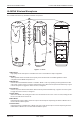
20. Power LED
Displays the battery power of the AL-MYNA. Green indicates good battery power. Red indicates low battery power.
Off indicates the microphone is turned off.
21. Headset Microphone Input
3.5mm jack for connection of the optional AL-HSM headset microphone. The internal microphone is disabled
when a headset is connected.
22. Mode LEDs
These two LEDs indicate the current mode of the AL-MYNA. When the right side blue LED is illuminated, the unit is
set to Mode 1. If both LEDs are illuminated, the unit is set to Mode 2.
NOTE: The unit MUST be set to Mode 1 to work properly with the LANcom system. If the volume up/down button is not
adjusting the microphone volume properly and you hear a pulsating noise through the loudspeakers, then the unit is
probably set to Mode 2. Change the unit to Mode 1 using the Mode button to correct the problem.
23. Lockout Switch
When this switch is set to the Lockout mode the unit works as a microphone only, no operation buttons function.
Also referred to as “Student Mode”.
24. IR Channel Switch
This slide switch sets the microphone channel “A” or “B”.
25. Belt Clip/Lanyard Clip
Used to attached AL-MYNA to belt for headset configuration or to the included lanyard for a lapel configuration.
26. Battery Cover
Conceals two “AA” rechargeable batteries, IR channel switch and Lockout mode switch.
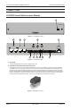
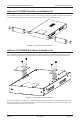
AL-MYNA-NEST
The LC372SR includes one (1) AL-MYNA-NEST charging station for the two (2) included AL-MYNA IR wireless micro-
phones.
27
28
30
29
Figure 6 - AL-MYNA-NEST
27. Microphone Charging Receptacles
Holds the microphones in place while charging. The microphones can be placed in forwards or backwards.