
User manual


PAGE 3 DOC: 1310B REV: 10-12
LC372SR SOUND REINFORCEMENT MODULE INSTALLATION INSTRUCTIONS
CONNECTIONS
LC372SR Sound Reinforcement Module
LC3 72SR
1
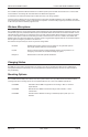
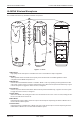
Figure 1 - LC372SR Front View
AUX AUDIO INPUT
+
-
S
+
-
S
+
-
S
+
-
V
M
SPKR
OUT
LINE
OUT
MUTE
POWER
FORM C RELAY OUTPUTS
NC
NO
C
NC
NO
C
NC
NO
C
NC
NO
C
ETHERNET/
IED MIDSPAN
Model# LANcom LC372SR
HANDSET
INTERFACE
AUX
INPUT
CALL SWITCHES
REMOTE MIC
IR RECEIVER INPUTS
3 4 52
7
8 9 10 11 12
6
Figure 2 - LC372SR Rear View
1. Power LED
This LED will illuminate when power is applied to the unit.
2. Call Switches and Remote Microphone RJ45 Ports
These ports are used to connect remote call switches (LC11CS or LC12DCS) or remote microphone modules
(LC372M) to the unit. This port provides access to the four (4) control lines available for the call switches. The
jumpers for each call switch determine which control line will be activated for each button. The four (4) control
lines are shared (wired in parallel) between both ports. The microphone input is a buffered input, allowing simul-
taneous usage when a remote microphone module is connected to both ports. Both microphones are mixed to
provide a single combined audio signal. Only one (1) LC372M may be connected to each port.
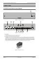
PIN 1
Figure 3 - RJ45 Male Connector