INSTALLATION INSTRUCTIONS LC372 SOUND REINFORCEMENT MODULE LC372SR SOUND REINFORCEMENT MODULE Installation Instructions REV: 10-12 DOC: 1307B
LC372SR SOUND REINFORCEMENT MODULE INSTALLATION INSTRUCTIONS IMPORTANT SAFETY INSTRUCTIONS 1. 2. 3. 4. 5. 6. 7. 8. 9. 10. Read these instructions. Keep these instructions. Heed all warnings. Follow all instructions. Do not use this apparatus near water. Clean only with dry cloth. Install in accordance with the manufacturer’s instructions. Do not install near any heat sources such as radiators, heat registers, stoves, or other apparatus (including amplifiers) that produce heat.
INSTALLATION INSTRUCTIONS LC372 SOUND REINFORCEMENT MODULE The LC372SR is powered via Ethernet cable from a LANcom power injector located near the device or in a remote telecommunications closet along with other data switch and distribution equipment. An internal fan and cabinet vents help keep the internal circuitry cool during operation. Contractor setup software tools are provided for device configuration and DSP adjustment.
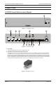
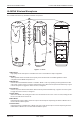
LC372SR SOUND REINFORCEMENT MODULE INSTALLATION INSTRUCTIONS CONNECTIONS LC372SR Sound Reinforcement Module 1 LC372SR Figure 1 - LC372SR Front View 2 3 4 5 6 IR RECEIVER INPUTS CALL SWITCHES REMOTE MIC AUX INPUT HANDSET INTERFACE AUX AUDIO INPUT + - S + - S SPKR LINE OUT OUT MUTEPOWER + - S + - M V ETHERNET/ IED MIDSPAN FORM C RELAY OUTPUTS NC C NO NC C NO NC C NO NC C NO Model# LANcom LC372SR 7 8 9 10 11 12 Figure 2 - LC372SR Rear View 1.
INSTALLATION INSTRUCTIONS LC372 SOUND REINFORCEMENT MODULE Pin Function Cat5 Color Code 1 Audio + Orange /W 2 Audio Orange 3 Switch out * Green /W 4 Switch out * Blue 5 Switch out * Blue/W 6 Switch out * Green 7 +48 VDC Brown /W 8 Ground Brown * Signal pin is determined by jumper setting on call switch plates. Table 1 - Call Switch and Remote Microphone RJ45 Connector Wiring 3. Aux Input Port This port is used to connect to an LC372AI Audio Input Plate.
LC372SR SOUND REINFORCEMENT MODULE Pin 5 6 7 8 INSTALLATION INSTRUCTIONS Function +48V DC Data TX – –48V DC (Ground) –48V DC (Ground) CAT5 Color Code Blue/W Green Brown /W Brown Table 4 - Power and Network RJ45 Connector Wiring 7. Aux Audio Input This connector provides an input for a balanced or unbalanced stereo (or mono) audio source. Both inputs are summed to mono and are controlled through the software.
INSTALLATION INSTRUCTIONS LC372 SOUND REINFORCEMENT MODULE AL-MYNA Wireless Microphone The LC372SR includes two (2) AL-MYNA IR wireless microphones. 13 14 15 16 17 22 18 23 19 24 20 21 25 26 14 Figure 5 - AL-MYNA 13. Microphone High quality internal microphone is used when the unit is in the handheld or lapel configuration. 14. IR LEDs These separate clusters of IR LEDs ensure quality c ommunications with an AL-IRDS regardless of which configuration the AL-MYNA microphone is in. 15.
LC372SR SOUND REINFORCEMENT MODULE INSTALLATION INSTRUCTIONS 20. Power LED Displays the battery power of the AL-MYNA. Green indicates good battery power. Red indicates low battery power. Off indicates the microphone is turned off. 21. Headset Microphone Input 3.5mm jack for connection of the optional AL-HSM headset microphone. The internal microphone is disabled when a headset is connected. 22. Mode LEDs These two LEDs indicate the current mode of the AL-MYNA.
INSTALLATION INSTRUCTIONS LC372 SOUND REINFORCEMENT MODULE 28. Microphone Charging LEDs These LEDs indicate the current charging status of each receptacle: Red = Charging, Green = Charged. 29. Battery Cover This provides a charging location for four additional rechargeable AA size batteries. 30. Additional Battery Charging LEDs These two LEDs indicate the current charging status of the additional battery charging locations: RED = Charging GREEN = Charged.
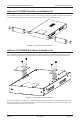
LC372SR SOUND REINFORCEMENT MODULE INSTALLATION INSTRUCTIONS Optional LC372RMK Rack-Mount Installation Kit The LC372RMK is available as an optional accessory used to allow mounting the LC372SR in a standard 19” equipment rack. Attach the two rack ears as shown in Figure 8 using the mounting screws included with the kit.
INSTALLATION INSTRUCTIONS LC372 SOUND REINFORCEMENT MODULE Figure 10 - LC372WMK Wall-Mount Installation Optional LC372PMK Pole-Mount Installation Kit The LC372PMK is available as an optional accessory to mount the LC372SR on a pole of up to 2”. This is a convenient solution when mounting the device in a room that has a video projector suspended on a ceiling mount. This allows you to place the LC372SR on the mounting pole between the projector and the ceiling.
LC372SR SOUND REINFORCEMENT MODULE INSTALLATION INSTRUCTIONS Next, attach the mounting bracket as shown in Figure 12 using the supplied mounting screws. Insert the U-shaped pole brackets and attach the retaining nuts loosely as you will tighten them later. Figure 12 - LC372PMK Mounting Hardware Installation Slide the unit on the pole as shown in Figure 13 and tighten the U-shaped mounting clamps snugly to support the unit.
INSTALLATION INSTRUCTIONS LC372 SOUND REINFORCEMENT MODULE Connect Unit to Other System Components Connect the field devices to the LC372SR as required. Figure 14 illustrates a typical room installation. Note that all connections are not shown in the example illustration.
LC372SR SOUND REINFORCEMENT MODULE INSTALLATION INSTRUCTIONS CONFIGURATION The SCS Endpoint Configurator application provides access to all the necessary setup operations that must be performed on an LC372SR Sound Reinforcement Module before it can be used in a system. It also provides access to additional setup features, such as EQ, that are configured upon installation and not adjusted as part of normal system operation.
INSTALLATION INSTRUCTIONS LC372 SOUND REINFORCEMENT MODULE Figure 18 - BOOTP Server Options Endpoint Device Discovery Once the application is running, it will scan the network for any LANcom devices and they will appear in the Discovery Window as shown below. The application will poll the devices at an interval that is accessible through the menu bar Tools -> Options. The default polling interval is 5 sec. and this is suitable for most circumstances.
LC372SR SOUND REINFORCEMENT MODULE INSTALLATION INSTRUCTIONS EQ Most of the adjustments made to the LC372SR are made through the LANcom SCS software. EQ adjustments are not accessible through the SCS software and must be made using the SCS Endpoint Configurator. First, highlight an LC372SR and then select the Edit sub-menu from the File menu as shown in Figure 20. There are two selections for PEQ. The one labeled Master is the main loudspeaker output of the device.
INSTALLATION INSTRUCTIONS LC372 SOUND REINFORCEMENT MODULE Center Freq. (HZ) Once you have selected a filter band, you can manually type in the frequency for the filter in this box. This allows you to quickly set the filter to a very precise value. When using one of the parametric bands, this frequency will control the center frequency of the filter. For the high-pass and low-pass filters, this will set the cutoff frequency. Gain (dB) Use this box to adjust the amount of cut or boost for the filter.
LC372SR SOUND REINFORCEMENT MODULE INSTALLATION INSTRUCTIONS SPECIFICATIONS Mechanical Dimensions ....................................................................8.50” W x 1.75” H x 13.625” D (215.9mm W x 44.5mm H x 346.1mm D) Mounting methods...................................Desk/Table Top Surface Mount (Standard), Optional Pole Mount Kit, Rack Mount Kit or Wall Mount Kit Connectors Ethernet/Power.....................................................................................................
INSTALLATION INSTRUCTIONS LC372 SOUND REINFORCEMENT MODULE NOTES REV: 10-12 DOC: 1310B PAGE 18
INSTALLATION INSTRUCTIONS Innovative Electronic Designs, LLC 9701 Taylorsville Road Louisville, KY 40299, USA REV: 10-12 LC372SR SOUND REINFORCEMENT MODULE +1.502.267.7436 phone +1.502.267.9070 fax www.iedaudio.