INSTRUCTION BOOK CONTROL SOLUTIONS
Atlas Copco Control solutions Elektronikon MK5 Swipe Instruction book Original instructions COPYRIGHT NOTICE Any unauthorized use or copying of the contents or any part thereof is prohibited. This applies in particular to trademarks, model denominations, part numbers and drawings. This instruction book is valid for CE as well as non-CE labelled machines. It meets the requirements for instructions specified by the applicable European directives as identified in the Declaration of Conformity.
Instruction book Table of contents 1 Elektronikon™ Swipe controller................................................................................... 3 1.1 CONTROLLER.....................................................................................................................................3 1.2 CONTROL PANEL................................................................................................................................ 5 1.3 ICONS USED........................................
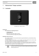
Instruction book 1 Elektronikon™ Swipe controller 1.1 Controller The Elektronikon™ Swipe controller Introduction The controller has following functions: • • • • Controlling the unit Protecting the unit Monitoring components subject to service Automatic restart after voltage failure (ARAVF) Automatic control of the unit The controller maintains the net pressure between programmable limits by automatically loading and unloading the unit. A number of programmable settings, e.g.
Instruction book Protecting the unit Shutdown If the element outlet temperature exceeds the programmed shutdown level, the unit will be stopped. The unit will also be stopped in case of overload of the drive motor or fan motor. Before remedying, consult the Safety precautions. Before resetting a warning or shutdown message, always solve the problem. Frequently resetting these messages without remedying may damage the unit.
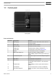
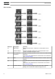
Instruction book 1.2 Control panel Control panel Parts and functions Reference Designation Function 1 Warning sign Flashes in case of a shut-down, is lit in case of a warning condition. 2 Service sign Is lit when service is needed. 3 Operation sign Is lit when the unit is running. 4 Voltage sign Indicates that the voltage is switched on. 5 Home button Tap this button to return to the Main screen. 6 Display The information is shown on the display.
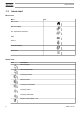
Instruction book 1.3 Icons used Menu icons Menu Icon Main screen Machine Settings Aux.
Instruction book Machine Control Mode, Remote Machine Control Mode, LAN Auto Restart After Voltage Failure (ARAVF) System icons Icon Description Basic User Advanced User Service User Change between screens (indication) Reset This chapter gives a general survey of available icons. Not all icons mentioned in this chapter are applicable to every machine. 1.4 Menu Procedure Starting from the main screen, use the left vertical swipe bar to navigate through the menu items.
Instruction book Menu structure 8 Reference Designation Function (1) Main screen Next to the main screen, a maximum of 3 extra values can be shown. (2) Machine settings Setpoints, Regulation settings and Control parameters can be viewed and modified through this menu. (3) Aux. Equipment parameters Settings for auxiliary equipment can be viewed and modified through this menu. This menu is only visible when the Access level is set to Advanced. See Controller settings.
Instruction book This is the main menu structure. The structure can be different depending on the configuration of the unit. Select or modify a setting Several settings can be modified. The process of selecting or modifying a setting anywhere in the menu is basically the same. Examples of modifiable settings Select In these examples, the upper value is selected. To select the lower value, swipe down on the left vertical swipebar. Modify To modify the selected value, tap the right vertical swipebar.
Instruction book Description Reference Designation Function (1) Screen information On the main screen, the screen information bar shows the current status of the machine. When scrolling through menus, the name of the current menu item is shown. (2) Access level icon The access level icon shows the current access level setting. See Controller settings menu to switch between User, Advanced or Service. (3) Control mode icon The control mode icon shows the current control mode setting.
Instruction book Example Setpoint used Starting from the main screen, swipe left until the Setpoint used screen is shown. To switch to a different setpoint, swipe up or down on the left vertical swipebar or tap next to the corresponding square. Manual unload Starting from the main screen, swipe left until the Manual unload screen is shown. Manual unload can only be activated when the machine is in LOAD and Local control. To manually unload the unit, tap on the left vertical swipebar.
Instruction book To reset the alarm, press the confirm button under the reset icon. To cancel without resetting, press the cancel button under the red ‘X’ icon. Before remedying, consult the Safety precautions. Before resetting a warning or shutdown message, always solve the problem. Frequently resetting these messages without remedying may damage the unit. 1.6 Machine settings menu Function The Machine Settings menu provides the ability to view and modify several machine settings.
Instruction book Setpoint 2 Starting from the Machine Settings menu, swipe left until the Setpoint 2 screen is shown. To select a load and unload setpoint, or to modify the values, see section Select or modify a setting. Regulation Starting from the Machine Settings menu, swipe left until the Regulation screen is shown. To select a menu item, or to change the setting, see section Select or modify a setting.
Instruction book The controller has a built-in function to automatically restart the compressor when voltage is restored after voltage failure. This function is deactivated in compressors leaving the factory and can only be modified after entering a password, please consult your supplier to activate this function. To select a menu item, or to change the setting, see section Select or modify a setting. 1.7 Auxiliary equipment parameters menu Function The Aux.
Instruction book SmartBox Starting from the Aux. Equipment parameters menu, swipe left until the Internal SmartBox screen is shown. (1) The reception quality of the internal antenna can be monitored. To select a menu item, or to change the setting, see section Select or modify a setting. 1.8 Data menu Function The Data menu provides the ability to view several important values. Swipe left to navigate to the following screens: • Counters • Inputs • Outputs Procedure To view the Data menu: 1.
Instruction book Counters Starting from the Data menu, swipe left until the Counters screen is shown. Select To select a different item, swipe up or down on the left vertical swipebar. Inputs Starting from the Data menu, swipe left until the Inputs screen is shown. Select To select a different item, swipe up or down on the left vertical swipebar. Outputs Starting from the Data menu, swipe left until the Outputs screen is shown.
Instruction book Swipe left to navigate to the following screens: • Next service • Safety valve test Procedure To view the Service menu: 1. Use the controller as a Service user . See Controller settings menu to change the user profile. 2. Tap the Home button on top of the screen to go to the main screen. 3. Swipe up on the left vertical swipebar until the Machine Settings menu is shown: Next Service Starting from the Service menu, swipe left until the Next Service screen is shown.
Instruction book On the horizontal swipebar, tap ‘V’ to confirm or ‘X’ to decline. 1.10 Controller settings menu Function The Controller Settings menu provides the ability to view and modify several settings of the controller. Swipe left to navigate to the following screens: • • • • • • Access Level Language Units CAN Settings Ethernet Settings Display Timeout Procedure To view the Controller Settings menu: 1. Tap the Home button on top of the screen to go to the main screen. 2.
Instruction book Enter a password The Service user profile is protected by a password. After selecting the Service user profile, the following screen pops up: The user can enter the password by swiping up or down on the right vertical swipebar to select the first digit. Tap ‘→’ to be able to enter the second digit. Once the 4 digits are entered, the user can confirm by tapping ‘V’ or decline by tapping ‘X’. Language Starting from the Controller Settings menu, swipe left until the Language screen is shown.
Instruction book Do not forget to turn on ethernet settings after changing these settings. Otherwise the controller can’t connect anymore! Display Timeout Starting from the Controller Settings menu, swipe left until the Display Timeout screen is shown. Display timeout is used to save energy and save the lifetime of the display. Timer starts after last operator actions on the push buttons or swipe bars. To modify the setting, see section Select or modify a setting. 1.
Instruction book • BOOT Software: nr 2920 7119 40 21
We stand by our responsibilities towards our customers, towards the environment and the people around us. We make performance stand the test of time. This is what we call — Sustainable Productivity. www.atlascopco.com No. 2920 7119 40 / 2019 - 03 - Printed in Belgium Atlas Copco Airpower NV. All rights reserved. Designs and specifications are subject to change without notice or obligation.