
Product Manual
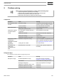
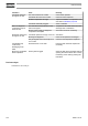
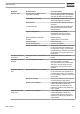
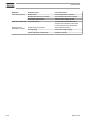
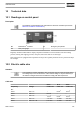
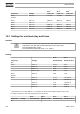
Table Of Contents
- Table of contents
- 1 Safety precautions
- 2 General description
- 3 Elektronikon controller
- 3.1 General description
- 3.2 Control panel
- 3.3 Icons used on the display
- 3.4 Main screen
- 3.5 Shut-down warning
- 3.6 Shut-down
- 3.7 Service warning
- 3.8 Scrolling through all screens
- 3.9 Calling up element and dew point temperatures
- 3.10 Digital inputs
- 3.11 Calling up running hours
- 3.12 Calling up motor starts
- 3.13 Calling up module hours
- 3.14 Calling up/resetting the service timer
- 3.15 Selection between Local, Remote or LAN control
- 3.16 Calling up/modifying CAN address control
- 3.17 Calling up/modifying IP, Gateway and Subnetmask
- 3.18 Calling up/modifying pressure band settings
- 3.19 Modifying pressure band selection
- 3.20 Calling up/modifying service timer settings
- 3.21 Calling up/modifying unit of temperature
- 3.22 Calling up/modifying unit of pressure
- 3.23 Automatic restart after voltage failure
- 3.24 Activating password protection
- 3.25 Calling up/modifying protection settings
- 3.26 Test screens
- 3.27 Web server
- 3.28 Programmable settings
- 4 Elektronikon Graphic Controller
- 4.1 General
- 4.2 Control panel
- 4.3 Icons used
- 4.4 Main screen
- 4.5 Calling up menus
- 4.6 Shutdown warning
- 4.7 Shutdown
- 4.8 Inputs menu
- 4.9 Outputs menu
- 4.10 Counters
- 4.11 Control mode selection
- 4.12 Service menu
- 4.13 Setpoint menu
- 4.14 Event history menu
- 4.15 General settings menu
- 4.16 Info menu
- 4.17 Week timer menu
- 4.18 Test menu
- 4.19 User password menu
- 4.20 Web server
- 4.21 Programmable settings
- 5 Installation
- 6 Operation
- 7 Preventive maintenance
- 8 Adjustments and servicing procedures
- 9 Problem solving
- 10 Technical data
- 11 Instructions for use
- 12 Guidelines for inspection
- 13 Pressure equipment directives
- 14 Declaration of conformity

SF 2
+
SF 4
+
SF 6
+
Frequency Voltage Cable size Cable size Cable size
60 Hz 380 V 3~
1.5 mm
2
1.5 mm
2
2.5 mm
2
UL/CUL
60 Hz 200 V 3~ AWG 12 AWG 10 AWG 8
60 Hz 230 V 1~ -- -- --
60 Hz 230 V 3~ AWG 12 AWG 10 AWG 8
60 Hz 460 V 3~ AWG 12 AWG 10 AWG 8
60 Hz 575 V 3~ AWG 14 AWG 14 AWG 14
10.3 Settings for overload relay and fuses
Attention
The indicated fuse value is the maximum value with regard to the short circuit protection
of the starter. The cable size used may specify fuses of a lower value.
Fuse specifications IEC: gL/gG
Fuse specifications CSA: HRC Form II - UL: Class 5
Settings
SF 2
+
SF 2
+
Frequency Voltage Overload relay Maximum fuse
IEC
50 Hz 230 V 1~ 16.2 A 25 A
230 V 3~ 9.7 A 40 A
400 V 3~ 5.6 A 10 A
400 V + N 3~ 5.6 A 10 A
60 Hz 380 V 3~ 5.8 A 10 A
UL/CUL
60 Hz 200 V 3~ 10.1 A
15/15/20 A
*
230 V 1~ 16.3 A
25/25/30 A
*
230 V 3~ 9.1 A
15/15/15 A
*
460 V 3~ 4.6 A
8/8/8 A
*
575 V 3~ 3.6 A
6/6/6 A
*
*
: Maximum fuses according HRCII-C, according Class K5 for units without refrigerant dryer and
according Class K5 for units with refrigerant dryer respectively.
SF 4
+
SF 4
+
SF 6
+
SF 6
+
Frequency Voltage Overload relay Maximum fuse Overload relay Maximum fuse
IEC
Instruction book
138 2920 7110 21