
Product Manual
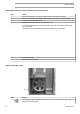
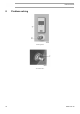
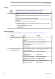
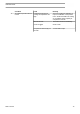
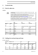
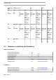
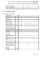
Table Of Contents
- Table of contents
- 1 Safety precautions
- 2 General description
- 3 Elektronikon Base Controller
- 3.1 ElektronikonTM Base Controller
- 3.2 Control panel
- 3.3 Icons used on the display
- 3.4 Main screen
- 3.5 Main function
- 3.6 Shutdown warning
- 3.7 Shutdown
- 3.8 Service warning
- 3.9 Scrolling through all screens
- 3.10 Calling up running hours
- 3.11 Calling up motor starts
- 3.12 Calling up module hours
- 3.13 Calling up loading hours
- 3.14 Calling up load solenoid valve
- 3.15 Calling up/resetting the service timer
- 3.16 Calling up/modifying pressure band selection
- 3.17 Calling up/modifying pressure band settings
- 3.18 Calling up/modifying the unit of temperature
- 3.19 Calling up/modifying the unit of pressure
- 3.20 Calling up/modifying backlight time
- 3.21 Activating automatic restart after voltage failure
- 3.22 Keyboard lock
- 4 Installation
- 5 Operating instructions
- 6 Maintenance
- 7 Adjustments and servicing procedures
- 8 Problem solving
- 9 Technical data
- 10 Instructions for use
- 11 Guidelines for inspection
- 12 Pressure equipment directives
- 13 Declaration of conformity

Frequency
(Hz)
Voltage (V) G7 G11 G15
60 380 12 20A 15,5 32A 18,5 32A
60 460 10 20A 13,5 32A 15 32A
CSA/UL DOL Over Load
relay FM1
(A)
Main fuses
(A) (class J
or RK) +
Disc.
Switch size
>=1,25 x
FLA, see
conn.
Diagram.
Over Load
relay FM1
(A)
Main fuses
(A) (class J
or RK) +
Disc.
Switch size
>=1,25 x
FLA, see
conn.
Diagram.
Over Load
relay FM1
(A)
Main fuses
(A) (class J
or RK) +
Disc.
Switch size
>=1,25 x
FLA, see
conn.
Diagram.
60 208-230/46
0
36,3-34,4 /
16,9
50-45 / 25 48-45 / 22,5 70-70/35
60 575 14 20 18,5 25
CSA/UL Star/Delta Over Load
relay FM1
(A)
Main fuses
(A) (class J
or RK) +
Disc.
Switch size
>=1,25 x
FLA, see
conn.
Diagram.
Over Load
relay FM1
(A)
Main fuses
(A) (class J
or RK) +
Disc.
Switch size
>=1,25 x
FLA, see
conn.
Diagram.
Over Load
relay FM1
(A)
Main fuses
(A) (class J
or RK) +
Disc.
Switch size
>=1,25 x
FLA, see
conn.
Diagram.
60 208-230/46
0
33,2-30 / 15 80-80 / 40
60 575 12 30
9.3 Reference conditions and limitations
Reference conditions
Air inlet pressure (absolute) bar 1
Air inlet pressure (absolute) psi 14.5
Air inlet temperature ˚C 20
Air inlet temperature ˚F 68
Relative humidity % 0
Working pressure bar(e) See Compressor data
Working pressure psi See Compressor data
Limitations
Maximum working pressure bar(e) See Compressor data
Maximum working pressure psig See Compressor data
Minimum working pressure bar(e) 4
Instruction book
2920 7191 00 77