
Product Manual
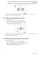
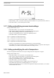
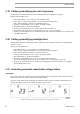
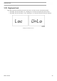
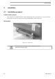
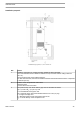
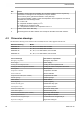
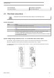
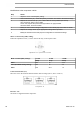
Table Of Contents
- Table of contents
- 1 Safety precautions
- 2 General description
- 3 Elektronikon Base Controller
- 3.1 ElektronikonTM Base Controller
- 3.2 Control panel
- 3.3 Icons used on the display
- 3.4 Main screen
- 3.5 Main function
- 3.6 Shutdown warning
- 3.7 Shutdown
- 3.8 Service warning
- 3.9 Scrolling through all screens
- 3.10 Calling up running hours
- 3.11 Calling up motor starts
- 3.12 Calling up module hours
- 3.13 Calling up loading hours
- 3.14 Calling up load solenoid valve
- 3.15 Calling up/resetting the service timer
- 3.16 Calling up/modifying pressure band selection
- 3.17 Calling up/modifying pressure band settings
- 3.18 Calling up/modifying the unit of temperature
- 3.19 Calling up/modifying the unit of pressure
- 3.20 Calling up/modifying backlight time
- 3.21 Activating automatic restart after voltage failure
- 3.22 Keyboard lock
- 4 Installation
- 5 Operating instructions
- 6 Maintenance
- 7 Adjustments and servicing procedures
- 8 Problem solving
- 9 Technical data
- 10 Instructions for use
- 11 Guidelines for inspection
- 12 Pressure equipment directives
- 13 Declaration of conformity

Text on drawings Translation or explanation
Dryer outlet cooling air
Dryer outlet cooling air
4.3 Electrical connections
Always disconnect the power supply before working on the electrical circuit!
General instructions
Step Action
1 Install an isolating switch near the compressor.
2 Check the fuses and the setting of overload relay. See Settings for overload relay and
fuses.
3 If fitted, check transformers for correct connection.
4 Connect the power supply cables to terminals L1, L2 and L3 (1X0) and the neutral
conductor (if applicable) to terminal (N). Connect the earth conductor.
The power supply cable delivered with the compressor must be protected by raceway or
by a suitable conduit system.
Specific voltage change instructions for G 7 – G 15 with 208 V / 230 V / 460 V cubicle
The standard voltage configuration for the compressor is mentioned on the data plate of the machine.
When the compressors leave the factory, the units are connected for 230 V / 3 phase.
To modify the wiring for an operating voltage of 208 V or 460 V, the main cubicle should be rewired as
described below:
G7 – G15 208/230/460V 60Hz
Instruction book
2920 7191 00 47