
Product Manual
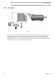
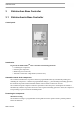
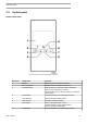
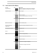
Table Of Contents
- Table of contents
- 1 Safety precautions
- 2 General description
- 3 Elektronikon Base Controller
- 3.1 ElektronikonTM Base Controller
- 3.2 Control panel
- 3.3 Icons used on the display
- 3.4 Main screen
- 3.5 Main function
- 3.6 Shutdown warning
- 3.7 Shutdown
- 3.8 Service warning
- 3.9 Scrolling through all screens
- 3.10 Calling up running hours
- 3.11 Calling up motor starts
- 3.12 Calling up module hours
- 3.13 Calling up loading hours
- 3.14 Calling up load solenoid valve
- 3.15 Calling up/resetting the service timer
- 3.16 Calling up/modifying pressure band selection
- 3.17 Calling up/modifying pressure band settings
- 3.18 Calling up/modifying the unit of temperature
- 3.19 Calling up/modifying the unit of pressure
- 3.20 Calling up/modifying backlight time
- 3.21 Activating automatic restart after voltage failure
- 3.22 Keyboard lock
- 4 Installation
- 5 Operating instructions
- 6 Maintenance
- 7 Adjustments and servicing procedures
- 8 Problem solving
- 9 Technical data
- 10 Instructions for use
- 11 Guidelines for inspection
- 12 Pressure equipment directives
- 13 Declaration of conformity

Electrical diagram
2205 0121 00 Service diagram G 7 – G 11 – G15 IEC
2205 0311 00 Service diagram G 7 – G 11 cULus/ cCSAus
2205 0311 01 Service diagram G15 cULus/ cCSAus
The complete electrical diagram can be found in the electric cubicle.
The complete electrical diagram can be found on the CD supplied with the machine.
2.8
Protection of the compressor
Safety valve on the compressor and on the vessel
Reference Designation Function
SV Safety valve To protect the air outlet system if the outlet pressure
exceeds the opening pressure of the valve.
Instruction book
2920 7191 00 23