
Product Manual
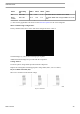
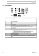
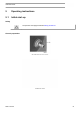
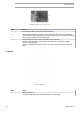
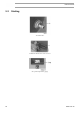
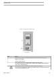
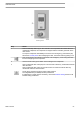
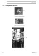
Table Of Contents
- Table of contents
- 1 Safety precautions
- 2 General description
- 3 Elektronikon Base Controller
- 3.1 ElektronikonTM Base Controller
- 3.2 Control panel
- 3.3 Icons used on the display
- 3.4 Main screen
- 3.5 Main function
- 3.6 Shutdown warning
- 3.7 Shutdown
- 3.8 Service warning
- 3.9 Scrolling through all screens
- 3.10 Calling up running hours
- 3.11 Calling up motor starts
- 3.12 Calling up module hours
- 3.13 Calling up loading hours
- 3.14 Calling up load solenoid valve
- 3.15 Calling up/resetting the service timer
- 3.16 Calling up/modifying pressure band selection
- 3.17 Calling up/modifying pressure band settings
- 3.18 Calling up/modifying the unit of temperature
- 3.19 Calling up/modifying the unit of pressure
- 3.20 Calling up/modifying backlight time
- 3.21 Activating automatic restart after voltage failure
- 3.22 Keyboard lock
- 4 Installation
- 5 Operating instructions
- 6 Maintenance
- 7 Adjustments and servicing procedures
- 8 Problem solving
- 9 Technical data
- 10 Instructions for use
- 11 Guidelines for inspection
- 12 Pressure equipment directives
- 13 Declaration of conformity

Condensate drain valve on air receiver
Step Action
1 Consult the installation instructions (see Installation).
2 Check that the electrical connections correspond to the local codes. The installation
must be earthed and protected against short circuits by fuses in all phases. An isolating
switch must be installed near the compressor.
3 Fit outlet valve (2), close it and connect the air net to the valve.
Connect condensate drain valve (Dm) and automatic drain outlet (Da) to a drain
collector. Close the valve.
Connect condensate drain valve (4) of the air receiver to a drain collector. Close the
valve.
Oil system
Oil level sight-glass
Step Action
1 Check the oil level.
The oil level sight-glass (SG) should be between 1/4 and 3/4 full.
Instruction book
52 2920 7191 00