
Product Manual
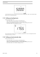
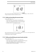
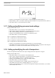


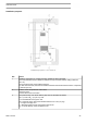

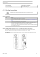
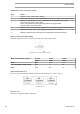
Table Of Contents
- Table of contents
- 1 Safety precautions
- 2 General description
- 3 Elektronikon Base Controller
- 3.1 ElektronikonTM Base Controller
- 3.2 Control panel
- 3.3 Icons used on the display
- 3.4 Main screen
- 3.5 Main function
- 3.6 Shutdown warning
- 3.7 Shutdown
- 3.8 Service warning
- 3.9 Scrolling through all screens
- 3.10 Calling up running hours
- 3.11 Calling up motor starts
- 3.12 Calling up module hours
- 3.13 Calling up loading hours
- 3.14 Calling up load solenoid valve
- 3.15 Calling up/resetting the service timer
- 3.16 Calling up/modifying pressure band selection
- 3.17 Calling up/modifying pressure band settings
- 3.18 Calling up/modifying the unit of temperature
- 3.19 Calling up/modifying the unit of pressure
- 3.20 Calling up/modifying backlight time
- 3.21 Activating automatic restart after voltage failure
- 3.22 Keyboard lock
- 4 Installation
- 5 Operating instructions
- 6 Maintenance
- 7 Adjustments and servicing procedures
- 8 Problem solving
- 9 Technical data
- 10 Instructions for use
- 11 Guidelines for inspection
- 12 Pressure equipment directives
- 13 Declaration of conformity

Ref. Action
4 Ventilation: the inlet grids and ventilation fan should be installed in such a way that any
recirculation of cooling air to the compressor or dryer is avoided.
The air velocity to the grids must be limited to 5 m/s (200 in/s).
The required ventilation capacity to limit the temperature of the compressor room can be
calculated from the following formula:
Q
v
= 0.92 N /
ΔT
Q
v
= Required ventilation capacity in m
3
/s
N = Shaft input of compressor in kW
ΔT = Temperature increase in the compressor room in °C
5 Position of the mains cable entry.
6 The drain pipes to the drain collector must not dip into the water of the drain collector.
4.2 Dimension drawings
The dimension drawing can be found on the CD-ROM, DVD or USB, supplied with the unit.
Dimension drawing Model
9828 0832 36 G 7, G 11, G 15 Pack, floor mounted
9828 0832 37 G 7, G 11, G 15 Pack, tank mounted
9828 0832 38 G 7, G 11, G 15 Full Feature, floor mounted
9828 0832 39 G 7, G 11, G 15 Full Feature, tank mounted
Text on drawings Translation or explanation
Emergency stop switch
Emergency stop switch
Power supply
Power supply
Cooling air and compressor inlet
Cooling air and compressor inlet
Cooling air outlet of compressor and motor
Cooling air outlet of compressor and motor
Service panel
Service panel
Compressor controller
Compressor controller
Oil level indicator
Oil level indicator
Compressed air outlet (G1/2” Female)
Compressed air outlet
Forklift openings
Forklift openings
Valve rotation
Valve rotation
Centre of gravity
Centre of gravity
Cubicle door fully open
Cubicle door fully open
Anchorpoints in base
Anchorpoints in base
Air receiver safety valve
Air receiver safety valve
Vessel anchor points
Vessel anchor points
Air receiver manual drain (G3/8” Female)
Air receiver manual drain
Dryer dewpoint indicator
Dryer dewpoint indicator
Condensate drain integrated dryer
Condensate drain integrated dryer
Dryer inlet cooling air
Dryer inlet cooling air
Instruction book
46 2920 7191 00