WARRANTY CERTIFICATE MAINTENANCE AND USER MANUAL - WARRANTY TO BE KEPT BY THE USER OF THE APPLIANCE ODYSSEO 2 ODYSSEO 2 HEAT PUMP WATER HEATER USING NON-HEATED AIR HEAT PUMP WATER HEATER USING NON-HEATED AIR Duration of the warranty* - Water heater (cylinder): 5 years in domestic installations 3 years in commercial installation - Electric elements and components parts: 2 years in domestic installations 1 year in commercial installations The warranty covering service items, or replacement unit, expire
WIRING DIAGRAM WIRING DIAGRAM STARTING YOUR HEAT PUMP WATER HEATER MAINTAINING YOUR HEAT PUMP WATER HEATER In order to protect the tank against corrosion, the water heater must remain switched on at all times. The wires in the electric cable are crimped. If you need to cut them, remember to crimp them again before connecting to the electric power supply.
Contents Important recommendations....................................................................................................... 2 Transportation & Storage ...................................................................................................................... 2 Safety instructions ................................................................................................................................. 2 Presentation of the product ............................................
Important recommendations Transportation & Storage The product can be inclined at 90° on one side. This side is clearly shown by a sign on the packaging. It is forbidden to incline the product on the other sides. An indicator shows whether the product has been transported and handled according to our recommendations. You are advised to make sure that these recommendations are followed. If the inclination indicator is red, our warranty is null and void.
Presentation of the product How it works The heat pump water heater uses unheated air to prepare domestic hot water. Heat energy extracted from the ambient air is absorbed by the refrigerant through heat transfer at the Evaporator. This energy is concentrated by the Compressor and then transferred by the Condenser into the hot water tank. This cycle is repeated after the refrigerant has cooled. A low energy fan ensures ambient air movement across the Evaporator.
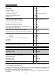
Technical characteristics Dimensions mm H 1897 x l 591 x D 674 Empty weight kg 90 Capacity of the tank L 270 Hot water / cold water connection 3/4 ’ ’ M Corrosion-proof protection Impressed current anode Minimum conductivity of the water μS/cm 40 Rated pressure Permissive excessive operating pressure kPa Mpa Electric connection (voltage / frequency) 560 1 240 V single phase 50 Hz Maximum total power input of the appliance W 2635 Average power input of the heat pump W 425 Maximum pow
Dimensions / components 1 Air outlet 10 Hot water inlet 2 Air inlet 11 Compressor 3 Fixed unit attachment 12 Evacuation of condensate 4 Fixed feet 13 Compressor permanent condenser 5 Cold water inlet 14 Evaporator 6 Pocket 15 Fan wiring 7 Sheath 16 Fan 8 Electric heating element (ceramic element) and mechanical safety device Regulation 17 Expansion valve 18 Cover 9 Not shown: - Manual - Condensate evacuation tube - -5- Dielectric coupling
Installation Selecting the location in compliance with IEC 60 529 Standard, AS60529:2004 Capable of withstanding a weight of at least 400 kg (the area under the water heater) The place where the appliance is installed must comply with protection index IP X1B according IEC 60 529 Standard and AS60529:2004 standard and in compliance with electrical wiring rules of Aus/Nz Configuration without ducts Configuration with ducts semi-ducted Type of room Unheated room at a temperature Room at least above freez
Recommended configurations 1st Configuration: installation without ducts in an unheated space (Volume > 20m3) FAN set to 0 (see Setting the regulation section, page 15). Examples of unheated rooms: - Garage: recovery of free heat released by the car engine after use or by other household appliances. Laundry : dehumidification of the room and recovery of heat released by washing machines and tumble driers. Semi-underground room: recovery of free heat released by the floor and walls of the basement.
Configuration tolerated under certain conditions Installation in an unheated space with one duct (outlet or inlet, volume > 20m3) FAN set to 1 (see Getting start section, page 14). Possible consequences: - The negative pressure in the room due to the expulsion of the exterior air may result in air entering through the doors and windows. Provide an air inlet (same diameter as the ducts) from the exterior in order to avoid sucking air from the heated space.
Installing the product 1- Transport the water heater to the place where it is to be installed. 2- Cut the cardboard skirting along the dotted lines. 3- Take the water heater off the pallet and place it by the hydraulic connection. +/- 1° MAXIMUM! The water heater must be installed on a smooth and horizontal floor. If this is not the case, it must be levelled using the supporting feet. If this precaution is not taken, problems may occur evacuating the condensates, resulting in frosting.
Hot water outlet Do not connect the hot water inlet directly to the copper pipes in order to avoid iron/copper galvanic couples (risk of corrosion). The hot water inlet (item 10 on page 5) must be fitted with a dielectric coupling (supplied with the appliance). If corrosion occurs on a hot water inlet that is not fitted with this protective device, our warranty does not apply.
Air connections. Your heat pump water heater can be fitted with ducting accessories that are not supplied with the water heater. If the volume of the room in which the thermodynamic water heater is installed is insufficient, it can be connected to 160 diameter air ducts. If the air ducts are not insulated, condensation may appear on them during operation. Therefore, it is essential to choose insulated air ducts. Poor ducting (crushed ducts, ducts that are too short or too many corners, etc.
Electric connections Caution: the water heater must be filled with water first, before making the electric connections (see Getting started section, page 14). The HPWH must remain connected to the main power supply at all times so that the operation of the (ACI) anti-corrosion protection of the water heater is ensured. Electrical work must be carried out by a licensed tradesperson and in accordance with Electrical Wiring Rules of Aus/NZ.
Electric connections FOR RIPPLE CONTROL: NEW ZEALAND ONLY 240 volt supply with 2 amp protection connected to the black auxiliary wire. Set HCHP parameter to ON, see page 15 setting the regulation. The diagram shown is only the functional configuration. Wiring details (ie. switching, fusing, method of isolation, neutrals and their locations must comply with statutory regulations and codes of practice.
Getting started 1. 2. Filling the water heater. Fill the water heater by opening all hot water taps and opening the cold water inlet to allow the water heater to fill and air in the system to be expelled. Close each hot water tap, as the flow becomes free of air. Check all piping for leaks. Check that water flows freely by gently operating the lever on the Pressure Temperature Relief valve. Power should not be turned on until the water heater is completely filled with water.
3. Setting the regulation Adjusting the temperature set point The temperature setting of your appliance is adjusted to 55°C in the factory. It can be adjusted simply by & directly on the default display. The lower the temperature setting of the heat pump, pressing the better the coefficient of performance (COP). Possible values: 45 to 62 Settings to be adjusted To open or close the setting menu, press + at the same time.
Use Control panel Back-lit display Navigation buttons in the modes Mode selection button Description of the pictograms: Symbol Name Description Compressor Status of the compressor: Compressor working Flashes slowly Fan Status of the fan: Low speed → Flashes slowly High speed → Flashes quickly Sensor Indication of the physical position of the sensors Sensor associated with the temperature on display → Flashes slowly Electric backup Status of the electric resistor: Electric backup working Flashes
Incoming air temperature Air temperature sensor in the flow of ambient air Evaporator temperature Temperature sensor on a cross in the evaporator Water temperature Water temperature sensor in the pocket Heat pump time Shows the working time of the water heater heat pump in hours Elec time Shows the working time of the water heater electric backup in hours Description of the modes Graphical icons Description Optimised management of the heat pump and the electrics for guaranteed comfort Heat pump o
ECO mode This mode uses the heat pump only to produce hot water. Under certain conditions, this mode may result in shortages of hot water (mainly due to air temperatures outside the operating range). BOOST mode BOOST mode can be used to force the heat pump and the electric backup to work at the same time in the event of high demand. The regulation automatically returns to the previous mode at the end of the cycle. ABSENCE mode This mode helps to protect the tank when the user is absent.
Adapting the mode of your appliance to your needs 1. Calculate your daily needs in terms of a number of showers (1 bath = 3 showers) Example: daily need = 3 showers + 1 bath => 6 showers 2.
Recommendations – Maintenance & Repairs Advice for users Flushing of sediment and draining : To flush or to drain the water heater, power must be turned off and then turn off the cold water supply to the water heater. The lever on the pressure and temperature relief valve should be opened but care should be taken so the lever does not snap back as it could damage the valve seat. The pressure in the water heater will be released when the lever is opened.
Maintenance by a qualified professional To protect the performance of your appliance for many years to come, it must be checked by a professional every 2 years. Switch off the electric power supply (circuit breaker, fuses, etc.). Drain the tank: close the cold water inlet (isolating valve), open a hot water tap, set the safety valve to the drain position. Remove the front cover. Disconnect the wires from the terminals of the thermostat. Remove the heating assembly.
Troubleshooting .
Fault diagnosis for professionals IMPORTANT Maintenance and repair operations must only be performed by qualified professionals. A specific menu is available to operate the system and help you with your diagnostic. This mode requires technical knowledge of the system. This mode is strictly for professionals only.
Check the resistance of the plug on the connector on the plug wiring and the condition of the wiring. Close the cold water supply using the isolating valve. Then open a tap in the hot water position. Wait for 10 minutes. If Cold water returns into the hot water a flow appears, identify the defective tap and/or check that the safety valve is circuit.
Sensor mapping curvesdes (Temperature vs Resistance) Courbes de correspondance sondes (Température vs Résistance) 120,0 Résistance [kOhms] Resistance [kOhms] 100,0 80,0 60,0 40,0 20,0 0,0 -20 0 20 40 60 80 100 120 Température [°C] Temperature [°C] IMPORTANT Never power the heating element directly. After-sales Only use original manufacturer's spare parts. When ordering from one of the brand's resellers, specify the precise type of water heater and the year of manufacture.
ATLANTIC HEAT PUMP WATER HEATER WARRANTY. Warranty Conditions 1. The heat pump water heater (hpwh) must be installed to plumbing and electrical services that meet all relevant statutory and local requirements of the region in which the system is installed. Relevant clauses of AS/NZS 3500 Plumbing & Drainage Code; and NZ G12 New Zealand Building Code – must be complied with by the Installer. 2. The hpwh requires a single phase 16 amp supply requiring a licensed electrician for connecting.
5. Where the hpwh fails due to misuse, accidental damage, acts of God, incorrect installation including being located in premises affected by frost or bad weather (humid, harsh or badly ventilated atmospheres) or unlicensed service repair work attempts. 6. Any damage resulting from power surge from supply such as accidental high voltage injection or lightning strike. 7.
ELECTRICAL RISKS: 1. Connection: All connections must be made in compliance with the manufacturer's drawings. In particular, make sure you do not neutralize the electric backup's thermostat (direct connection forbidden) 2. To avoid the power supply cable heating up, use the cable type and cross section given in the installation manual. All regulations in force must be respected. 3. Make sure that there is an electric circuit protection upstream from the device. 4.
WIRING DIAGRAM WIRING DIAGRAM STARTING YOUR HEAT PUMP WATER HEATER MAINTAINING YOUR HEAT PUMP WATER HEATER In order to protect the tank against corrosion, the water heater must remain switched on at all times. The wires in the electric cable are crimped. If you need to cut them, remember to crimp them again before connecting to the electric power supply.
WARRANTY CERTIFICATE MAINTENANCE AND USER MANUAL - WARRANTY TO BE KEPT BY THE USER OF THE APPLIANCE ODYSSEO 2 ODYSSEO 2 HEAT PUMP WATER HEATER USING NON-HEATED AIR HEAT PUMP WATER HEATER USING NON-HEATED AIR Duration of the warranty* - Water heater (cylinder): 5 years in domestic installations 3 years in commercial installation - Electric elements and components parts: 2 years in domestic installations 1 year in commercial installations The warranty covering service items, or replacement unit, expire