
User Guide

System 20 LCR and SR InWall Speakers
● ● ● ● ● ● ● ● ● ● ●
7
● ● ● ● ● ● ● ● ● ● ●
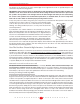
IMPORTANT: Exercise extreme care before making any wall cuts to ensure that you will not cut through
any wires, pipes, or other items that may be in the wall. You may sometimes, but not always, be able to
determine the approximate location of wires and pipes by looking at the locations of nearby outlets
and plumbing. But their presence or absence is never an assurance that there is not something within
the wall cavity.
There must be a minimum depth behind the wall face of 3 5/8 (92mm). As noted above, be sure to keep the
edges of the cut out at least 1 inch (25mm) away from any stud or obstruction. The speaker assembly itself (the
part with the drivers mounted in it, the trimming bezel, etc.) is designed to mount to the Installation Bracket
after it has been installed within the wall.
Step 1. Tilt one corner of the Installation Bracket into the opening and continue to slide it fully into the wall cavity
until it fits completely into the cut out. Be sure to position the side extensions so they press against the inside
of the wall.
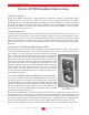
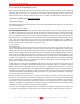
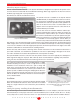
Step 2. Carefully insert the tabs into the Installation Bracket as
shown in Fig. 7. They are a tight fit and are best installed by
“clamping” them with your hand as shown in Fig. 6. Alternately,
there are predrilled holes in the side flanges of the Installation
Bracket that may be used to hold the assembly to the wall board
with #6 self-threading screws, instead of using the tabs. These
screws will be hidden by the speaker’s bezel when it is mounted.
Step 3. After the Installation Bracket is fixed in place note that
there are holes near the center of the long sides that can be
used to secure feed wiring using the included nylon wire ties.
Step 4. Strip about ˚” of insulation from the connecting wires.
Connect them to the appropriate push terminal on the rear of
the speaker assembly, being careful to observe polarity (posi-
tive to the red terminal, negative to the black terminal). Typically, with standard “zip” cord wiring the marked wire
is used for the positive lead. Markings typically consist of a thread within one conductor, printing on the wire’s
insulation, a ridge or ridges on the insulation, or a flat side to the insulation.
Step 5. Carefully position the speaker assembly into the wall cutout and Installation Bracket. Check that it’s
level and then attach the speaker to the Installation Bracket with the included 3 inch #6 self-tapping screws. (If
the assembly is not level, you can oversize the wall opening very slightly to allow straightening the bracket and
speaker.)
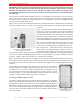
Step 6. Tighten the mounting screws, which in turn will cause the bezel and the
Installation Bracket to clamp the wall board between them.
Be very careful not to
overtighten the screws as this can make the grille difficult or impossible to install.
The outer trim bezel has been specially designed to flex and conform to the wall-
board. This makes for a good seal and eliminates rattles but it also means that the
speaker mounting screws should be snug, but not overly tight.
Installing and Removing the Grille
The grille is packed separately in the box with System 20 speakers. To install the
grille, press it carefully into the opening in the frame assembly. Since it’s designed to
fit snugly, please take your time and use care when installing the grille. Remove the
grille from the speaker using an awl or other pointed object in a grille opening near
one of the corners. Slowly pry the grille out, being careful not to damage the speaker’s
frame or its finish. If the grille is difficult to install, try loosening the speaker installa-
tion screws slightly.
Fig. 6
Installing the tabs in the Installation Bracket.
Shown outside the wall for clarity.
Fig. 7
The Installation Bracket mounted
in the wall using the tabs