
User Guide

System 20 LCR and SR InWall Speakers
● ● ● ● ● ● ● ● ● ● ●
6
● ● ● ● ● ● ● ● ● ● ●
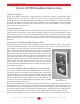
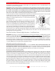
Infrared Eye Repeater Opening
There’s a cutout located on the front of the System 20 LCR that’s designed to accept most IR repeater receiv-
ers. This cutout is located under the round Atlantic Technology “Wave logo” adjacent to the woofer. To remove
the Wave logo simply push it out from behind.
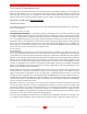
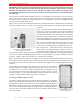
Rear Enclosure and Internal Wall Treatment
An optional enclosure is available for the System 20 LCR
(IN-BOX-20LCR). It’s designed to be used in new construc-
tion and must be installed before the wall board is applied.
The benefits this enclosure provides include optimum vol-
ume for the woofer and a level of sound isolation for the
adjacent room. The optional enclosure comes with the In-
stallation Bracket pre-installed.
You can also create an enclosure within the wall that pro-
vides the required cubic volume. The larger the volume, the
better the bass response will be, up to 1 cubic foot. Beyond
this size there will be little if any effective performance gain.
Please note that there is very little room behind the 20 LCR
in a standard “2 x 4” wall cavity (approx. 1/4 inch, 6mm), so
the back of any enclosure box must be made from relatively
thin materials, yet it should not physically contact the back of the speaker. Typically then, the back wall material
will be roughly 1/8 to 1/4 inch (3 to 6mm) thick. You can also build a fire break type of enclosure by installing 2
x 4 or 2 x 6 cross members in the wall at appropriate positions. For the best performance the edges of the studs
should be caulked with an all weather silicone caulking material.
Fill the wall cavity with insulation, observing all the relevant instructions from the insulation manufacturer. If
you‘ve built a back box, use tufted Dacron (available at craft stores as pillow filling) or fiberglass in the enclo-
sure. There should be no insulation directly behind the actual speaker assembly.
The System 20 SR is much less critical of wall cavity volume than the LCR, and is typically not called upon to
deliver significant deep bass response. Still, follow the above recommendations regarding cavity insulation.
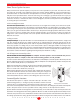
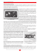
Using The Rear Installation Bracket Kit For Rough-In in New Construction
The required Installation Bracket kit (IN-INST-20LCR or 20SR)
includes everything necessary to create a rough-in kit for easing
installation in new construction. There are a pair of “wings” that
attach to the rear bracket and are then attached to the studs. The
rear Installation Bracket then acts as both a place holder for the
speaker system, in addition to being the clamping device when the
speaker is mounted in the wall. Instructions for its use are included
with the kit. Once the Installation Bracket has been installed pro-
ceed as detailed below.
Installation
The following instructions cover both the System 20 LCR and SR.
When the Installation Bracket has been used with the included
wings as a rough-in device in new construction, proceed directly
to Step 4.
Cutting the Opening - Installing the Installation Bracket
After determining the best location for the speaker as outlined above, use the template (enclosed in the Instal-
lation Bracket kit) to cut the proper size hole in a retrofit installation (LCR - 17 13/16” x 9 3/8”, SR - 11” x 14 3/8”).
It’s very important to cut the hole level as there is no “play” between the speaker and the Installation Bracket.
FIg. 4
Set up for horizontal installation
Fig 5
The mid/high baffle shown removed for clarity with the
removable leveling spacer. The spacer can be
removed for tilting without disconnecting the assembly
from the speaker.