High Performance In-Wall Theater System Speaker Instruction Manual IWTS-30 LCR THX Ultra2
Safety Precautions IWTS-30 LCR In-Wall Theater System Speaker Table of Contents 2 Model IWTS-30 LCR 2 What's THX? 2 Important Considerations Before Installation 2 2 3 Recommended Wire Sizes Location Considerations Room Acoustics 3 3 4 Using the 30 LCR's Tiltable M-T-M Baffle Stereo Music Listening Home Theater Systems 3 Speaker Placement 5 Installation of the IWTS-30 LCR in Existing Construction 5 Installation of the IWTS-30 LCR in New Construction with Optional Back Box 5 Installation of the IWTS
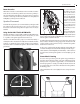
Speaker Placement Instruction Manual Room Acoustics To rotate the baffle, hold the baffle on the front and rear flat surfaces (being careful not to press on the midrange or tweeter diaphragms) and turn the M-T-M baffle to its desired position. Do not exceed 90˚ of rotation to avoid putting undue stress on the midrange-tweeter lead wires. Hard surfaces create lots of sound reflections in the room while soft surfaces tend to absorb sound.
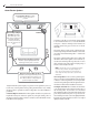
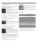
Home Theater Placement IWTS-30 LCR In-Wall Theater System Speaker Home Theater Systems Front Speaker Array should be placed as close to ear level as possible. Left Center Optional Dipole/Bipole Speakers should be placed directly to the sides of the seating area and approximately 1-2 feet (.3-.6 meter) above the listener’s ear level. Right Subwoofer Sometimes, people like to use the Center channel 30 LCR in its horizontal orientation.
Installation Instruction Manual Installation of the IWTS-30 LCR in Existing Construction NOTE: We always recommend a professional be involved in the installation of the IWTS-30 LCR. The IWTS-30 LCR can be easily mounted in most any standard wall material, from ½ to 1½ inches thick. Use the grille/ frame assembly GFR-626/30, sold separately. The GFR’s rotating wall clamps firmly fix it to the wall surface after the proper cutout has been made.
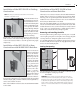
Installation IWTS-30 LCR In-Wall Theater System Speaker Installing the Mounting Frame Speaker Connection and Assembly The clamping mechanism allows the wall material to range from ½ to 1½ inches (13 to 38 mm) in thickness. There must be a minimum depth behind the wall face of 35⁄8” (92 mm). As noted above, be sure to keep the edges of the cutout at least 1½inch (38mm) away from any stud or obstruction, as the rotating clamps will not operate properly if you don’t.
Front Panel Controls Instruction Manual Front Panel Controls IR Knockout There’s an IR “knockout” plug in the upper right corner of the front baffle. If you are using a multi-room control system, you can install a standard IR receiver in the knockout hole. The IWTS-30 LCR has three controls that help optimize the speaker’s performance regardless of mounting location or room acoustics.
343 Vanderbilt Avenue Norwood, MA 02062 (781) 762-6300 www.atlantictechnology.