In-Wall THX Ultra2 Theater System Speakers Instruction Manual IWTS-155 LCR Speakers
Safety Precautions IWTS-155 LCR In-Wall THX Ultra2 Theater System Speakers Table of Contents 2 Model IWTS-155 LCR 3 Important Considerations Before Installation 3 3 3 Recommended Wire Sizes Location Considerations Room Acoustics 3 4 Stereo Music Listening Home Theater Systems 5 5 6 6 6 6 Removing and Installing the Grille Cutting the Opening Installing the Mounting Frame Painting the Speaker Assembly Speaker Connection and Assembly Installing the Speaker Enclosure Into the Frame 7 7 7 7 HF (High
Speaker Placement Instruction Manual Important Considerations Before Installation Recommended Wire Sizes The longer the wire run, the heavier the wire should be. Use the following recommendations as a guide for your installation. And if you’re in doubt, remember that it never hurts to get the next heavier grade of wire. Also note that lower gauge numbers equal heavier wire sizes. Wire Run Wire Gauge: <15 ft. 16 ga. 15 to 30 ft. 14 ga. >30 to 50 ft. 12 ga.
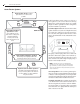
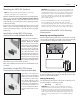
Home Theater Placement IWTS-155 LCR In-Wall THX Ultra2 Theater System Speakers Home Theater Systems Front Speaker Array should be placed as close to ear level as possible. Center Left Optional Dipole/Bipole Speakers should be placed directly to the sides of the seating area and approximately 1-2 feet (.3-.6 meter) above the listener’s ear level. Right Subwoofer Optional Direct Radiator Speakers should be placed slightly behind the listening position, above ear level.
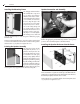
Installation Instruction Manual Mounting the IWTS-155 Speakers NOTE: We always recommend a professional be involved in the installation of the IWTS-155 LCR, if at all possible. The IWTS-155 LCR can be easily mounted in most any standard wall material, from ½ to 1½ inches thick. Use the grille/frame assembly GFR-155, sold separately. The GFR's rotating wall clamps firmly fix it to the wall surface after the proper cutout has been made.
Installation IWTS-155 LCR In-Wall THX Ultra2 Theater System Speakers Installing the Mounting Frame The clamping mechanism allows the wall material to range from ½ to 1½ inches (13 to 38 mm) in thickness. There must be a minimum depth behind the wall face of 3 5⁄8” (92 mm). As noted above, be sure to keep the edges of the cutout at least ½ inch (13 mm) away from any stud or obstruction, as the rotating clamps will not operate properly if you don’t.
Front Panel Controls Instruction Manual 7 Front Panel Controls The IWTS-155 has two controls that help optimize the speaker’s performance regardless of mounting location or room acoustics. HF (High Frequency) Level Control This control adjusts the relative level of high frequency output to compensate for varying room acoustics or placement behind a screen. “+” is for absorptive, acoustically “dead” rooms (or when the speaker is behind a movie screen).
343 Vanderbilt Avenue Norwood, MA 02062 (781) 762-6300 www.atlantictechnology.