Atkinson Dynamics Intercoms Models AD-26, AD-27, AD-56, and AD-57 Installation and Service Instructions Address all communications and shipments to: 2645 Federal Signal Drive University Park, IL 60466-3195 (888)751-1500
INSTALLATION AND SERVICE INSTRUCTIONS FOR ATKINSON DYNAMICS HEAVY-DUTY INTERCOMS SAFETY MESSAGE TO INSTALLERS, USERS AND MAINTENANCE PERSONNEL It is important to follow all instructions shipped with this product. This device is to be installed by a trained electrician who is thoroughly familiar with the National Electrical Code and will follow NEC Guidelines as well as local codes. Marine installations shall be in accordance with Title 46, CFR, Parts 110-113.
Additional Model Information Letter Group Function/Feature “A” Call button “C” Master mode “D” Slave mode Number Group “-1” Remote power “-2” Provisions for external talk/listen switch (Foot pedal ready) “-3” External call contacts for auxiliary signal “-4” Extreme temperature use (-50°F to 150°F) “-6” Designed for use in a zoned system “-7” Provisions for hand-held noise canceling microphone “-8” Miscellaneous Additional pre-amp for use with remote slave speaker “-M22” Equipped with
HEADSET MICROPHONE WITH-BELT-SWITCH: “M34” Headset Microphones and Belt Switches are an additional option for environments with a high level of ambient noise. Keying the belt switch overrides the default mode of the intercom and enables audio transmission to all Master units in the intercom system. Figure 5 illustrates a common intercom system where a headset microphone and belt switch are used. REMOTE POWER: “-1” Models are designed to provide power to “-1” remote intercom units.
B. Unpacking. After unpacking the Atkinson Dynamics Intercom, examine it for damage that may have occurred in transit. If the equipment has been damaged, do not attempt to install or operate it, and file a claim immediately with the carrier stating the extent of the damage. Carefully check all envelopes, shipping labels and tags before removing or destroying them. Before attempting to install the intercom, be sure that all parts listed in the KIT CONTENTS LIST have been supplied. C. Kit Contents List. Qty.
F. Service. 1. General. Federal Signal will service your equipment or provide technical assistance with any problems that cannot be handled locally. Any units returned to Atkinson Dynamics for service, inspection, or repair must be accompanied by a Return Material Authorization. This R.M.A can be obtained only from the factory by calling (888)751-1500. At this time a brief explanation of the service requested or the nature of the malfunction, should be given.
2. Replacement Parts. WARNING Replace fuse with GMC-1/2 only. DO NOT substitute.
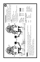
-7- BLK WHT GRN SEE POWER CONNECTIONS WHT BLK AUDIO CABLE 3 1 1WATT 1K 4 2 * BLK WHT GRN REMOTE B WHT BLK AUDIO CABLE 3 1 290A3693 TO OTHER INTERCOMS Reminders: • Before installing remote intercoms, precautions should be taken to prevent feedback between two or more remotes in close proximity and acoustically reflective areas. • 16–20 gauge low voltage audio cable. Twisted pair not required.. • Shielded audio cable not required unless operating in high electromagnetic fields.
SEE POWER -8- BLK WHT GRN WHT BLK 3 1 1K 1WATT COMMON AUDIO 5 * 4 2 BLK WHT GRN WHT BLK REMOTE B Reminders: • Before installing remote intercoms, precautions should be taken to prevent feedback between two or more remotes in close proximity and acoustically reflective areas. • 16–20 gauge low voltage audio cable. Twisted pair not required. • Shielded audio cable not required unless operating in high electromagnetic fields. Ground one end of the shield to earth ground.
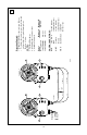
SEE POWER -9- * BLK WHT GRN * CONNECTIONS 2 REMOTE A BLK WHT GRN 3/16-20 AWG 3 1 1WATT 1K 2 WHT BLK (+) DC POWER GRN COMMON AUDIO REMOTE B 290A3695 3 1 AD-27-1 AD-57-1 Remote A Remote B AD-26-1 POWER CONNECTIONS: BLK +DC Power 12/24V Models HOT 120/240V Models WHT Common 12/24V Models Neutral 120/240V Models GRN Earth Ground 120/240V Models only Power Not applicable 120V 50/60Hz 240V 50/60Hz Operating Principle: • When one talks, the other stations will hear.
-10- BLK WHT GRN BLK 3 CONTROL GRN 1 * BLK 1K WHT 2 1 WATT AUDIO BLK WHT GRN 3 COMMON * 2 GRN 5 4 1 WHT 3 1 MASTER "B" 2 1 BLK WHT GRN BLK 3 WHT 2 GRN 1 SLAVE Master A AD-26C-7 AD-27C-7 AD-56C-7 AD-57C-7 Master B AD-26C AD-27C AD-56C AD-57C Slave AD-26D AD-27D AD-56D AD-57D 290A3696 POWER CONNECTIONS: BLK +DC Power 12/24V Models HOT 120/240V Models WHT Common 12/24V Models Neutral 120/240V Models GRN Earth Ground 120/240V Models only Before installing remote intercoms, pr
* -11COMMON WHT 1 WATT 1K AUDIO 6 BLK 5 3 1 7 * BLK WHT GRN WHT BLK 290A3702 TO OTHER INTERCOMS Remote A AD-26A-M34 AD-27A-M34 AD-56A-M34 AD-57A-M34 POWER CONNECTIONS: BLK +DC Power 12/24V Models HOT 120/240V Models WHT Common 12/24V Models Neutral 120/240V Models GRN Earth Ground 120/240V Models only Before installing remote intercoms, precautions should be taken to prevent feedback between two or more remotes in close proximity and acoustically reflective areas.
6 POWER CONNECTIONS: BLK +DC Power 12/24V Models HOT 120/240V Models WHT Common 12/24V Models Neutral 120/240V Models GRN Earth Ground 120/240V Models only REMOTE SLAVE STATION 1 NOTES 1. Speaker/Microphone 2. Off/On Speaker Volume Control 3. Talk/Listen Switch 4. Remote Slave Station Model AD-SV-25 Operating Principle: 1. Slave station is both a speaker and a microphone. 2. Master is normally in “Listen” mode until the talk button is pressed to talk to remote. 3.
SPEAKER 7 5 BLK 1 WHT 2 MASTER 1 200 FT. MAX. 2 3 AUDIO COMMON 1K 1WATT 4 SEE POWER BLK * CONNECTIONS * WHT BLK WHT GRN 290A3743B Operating Principle: 1. Slave station is both a speaker and a microphone. 2. Master is normally in “Listen” mode until the talk button is pressed to talk to remote. 3. Outgoing and incoming volumes are controlled by separate controls on master. NOTES: 1. Speaker/Microphone 2. Off/On/Speaker volume control 3. Talk/Listen switch 4. Outgoing Volume Control 5.
-14- NOTES: 1. Speaker/Microphone 2. Off/On/Speaker Volume Control 3. Press-to-Talk Switch 4. #137144 Hand-held, noisecancelling microphone with push-to-talk switch Operating Principle: 1. Masters normally listen to slave. 2. Slave talks to masters “hands-free”, without having to press a talk switch. 3. When any master talks, slave hears. Other master will hear. 4. To talk into master, press talk switch and speak into speaker/ microphone. Release talk switch to listen. 5.
SEE POWER -15- * TO OTHER INTERCOMS BLK WHT GRN * CONNECTIONS 2 REMOTE A WHT BLK 3 1 1K 1WATT * 2 COMMON AUDIO BLK WHT GRN WHT BLK REMOTE B RED GRN 290A4065 4 3 1 AD-26 AD-27 AD-56 AD-57 Remote A POWER CONNECTIONS: BLK +DC Power HOT WHT Common Neutral GRN Earth Ground 12-18VDC 120V 50/60Hz 22-30VDC 240V 50/60Hz Power 12/24V Models 120/240V Models 12/24V Models 120/240V Models 120/240V Models only AD-26-2 AD-27-2 AD-56-2 AD-57-2 Remote B NOTES: 1. Speaker/Microphone 2.
SEE POWER BLK WHT GRN * CONNECTIONS * 2 MASTER "A" -16- BLU RED 4 POWER CONNECTIONS: BLK +DC Power HOT WHT Common Neutral GRN Earth Ground BLK GRN WHT BLK WHT GRN BLK * 2 WHT GRN 3 1 MASTER "B" 1 WATT 1K BLK WHT GRN COMMON BLK WHT GRN SLAVE CONTROL AUDIO * 2 12/24V Models 120/240V Models 12/24V Models 120/240V Models 120/240V Models only 3 1 290A4066 Power 12-18VDC 120V 50/60Hz 22-30VDC 240V 50/60Hz Master A AD-26C-2 AD-27C-2 AD-56C-2 AD-57C-2 Master B AD-26C AD-27C
-17* BLK WHT GRN 5 4 1 2 ** 6 BLK RED TALK TALK COM. WHT LISTEN COM. * GRN BLK WHT GRN LISTEN ** MASTER WALL MOUNT INTERCOM 3 MASTER DESK SET Operating Principle: 1. Master can select (via master switch box) to talk to any one or more remotes. 2. Any remote can initiate a call to Master regardless of selector switch being on or off. Remote must specify its location. Remotes cannot talk to other remotes. 3. To talk into intercom, press talk switch and speak into speaker/microphone.
12 MASTER SPEAKER 5 4 GRN 1 WHT 2 CONTROL SLAVE 1 200 FT. MAX. 2 AUDIO MASTER SPEAKER 1K 1WATT 3 SEE POWER * CONNECTIONS * COMMON RED BLK GRN WHT BLK WHT 290A4068 OPERATING PRINCIPLE: 1. Master station is both a speaker and a microphone. 2. Master is normally in “Listen” mode until the PTT (press-to-talk) switch is pressed to talk to slave. 3. Outgoing and incoming volumes are controlled by separate controls on slave. 4.
-19- * AUDIO LINE BLK WHT GRN * CONNECTIONS SEE POWER 4 2 REMOTE "A" GRN RED WHT BLK AUDIO CABLE 3 1 1 WATT 1K * 2 1 BLK WHT GRN REMOTE "B" WHT BLK 3 TO OTHER INTERCOMS AUDIO CABLE 5 AUXILLIARY SIGNALING DEVICE - POWER 290A4069 + POWER AD-26-3 AD-27-3 AD-56-3 AD-57-3 12-18VDC 120V 50/60Hz 22-30VDC 240V 50/60Hz POWER CONNECTIONS: BLK +DC Power HOT WHT Common Neutral GRN Earth Ground Remote A Power 12/24V Models 120/240V Models 12/24V Models 120/240V Models 120/240V Model
-20- * * BLK WHT GRN SEE POWER CONNECTIONS 4 2 MASTER BLK RED CONTROL (+) POWER BLK RED GRN WHT AUDIO COMMON 1K GRN 1 WATT 2 WHT 3 1 1 REMOTE 290A4070 3 AD-27C-1-M22 Master Remote AD-26-1-2 POWER CONNECTIONS: BLK HOT 120/240V Models WHT Neutral 120/240V Models GRN Earth Ground 120/240V Models Power Not applicable 120V 50/60Hz NOTES: 1. Speaker/Microphone 2. Off/On/Speaker Volume Control 3. Press-To-Talk Switch 4.
-21- * BLK WHT GRN SEE POWER * CONNECTIONS 4 2 MASTER BLK CONTROL BLK GRN WHT BLK WHT GRN COMMON * WHT 1K AUDIO 1 WATT 2 GRN 3 1 1 SLAVE 290A4071 3 Master AD-27C-M22 Slave AD-27-2W3 POWER CONNECTIONS: BLK HOT 120/240V Models WHT Neutral 120/240V Models GRN Earth Ground 120/240V Models Power 120V 50/60Hz NOTES: 1. Speaker/Microphone 2. Off/On/Speaker Volume Control 3. Press-To-Talk Switch 4.
8 4 2 RED BLK GRN WHT SPKR HEADSET -22BLK COMMON BLK WHT 12/24V Models 12/24V Models Master B AD-26C-1-M34 WHT RED GRN 7 CONTROL Master A AD-26C-1-M80 SLAVE HEADSET + DC POWER 1WATT 1K SPKR RED 4 AUDIO 6 2 1 GRN 3 5 1 POWER CONNECTIONS: RED +DC Power WHT Common Power 12-18VDC MASTER "A" SPKR WHT BLK RED GRN 7 HEADSET MASTER "B" Slave AD-26D-1-M34 4 2 1 - 290A4072 ( ) DC POWER (+) 3 NOTES: 1. Speaker/Microphone 2. Off/On/Speaker Volume Control 3.
2 -23- ( ) - COMMON WHT POWER CONNECTIONS: BLK +DC Power WHT Common * 4 Master B AD-26C-1-2 AD-56C-1-2 12/24V Models 12/24V Models OR YEL BRN RED 1K 1WATT (+ DC POWER FROM MASTER "B") * (CONTROL FROM MASTER "B") WHT BLK CONTROL RED GRN BLU Master A AD-26C-1 AD-56C-1 3 * OBSERVE COLOR CODE + DC POWER 5 BLK 2 AUDIO 3 1 MASTER "B" GRN Power 12-18VDC 22-30VDC POWER (+) MASTER "A" 2 1 AUDIO Slave AD-26D-1 AD-56D-1 COMMON CONTROL + DC POWER WHT RED BLK GRN SLAVE
* BLK WHT GRN 2 1 SEE POWER * CONNECTIONS MASTER 3 RA WHT 5 -24RC RB WHT GRN BLK RED WHT GRN BLK RED WHT GRN BLK BLK GRN RED TO OTHER REMOTES MASTER SELECTOR SWITCH BOX RED 4 * 2 1 * 2 1 BLK WHT GRN REMOTE "B" TO REMOTE RB BLK WHT GRN REMOTE "A" 290A4074 3 3 Master AD-27C-1 POWER CONNECTIONS: BLK HOT WHT Neutral GRN Earth Ground Power 120V 50/60Hz 120/240V Models 120/240V Models 120/240V Models Remotes AD-27D-M49 NOTES: 1. Speaker/Microphone 2.
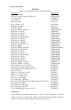
-25- BLACK +DC POWER CONTROL CONTROL +DC POWER +DC POWER AUDIO AUDIO AUDIO AUDIO AUDIO AUDIO +DC POWER +DC POWER CONTROL +DC POWER AUDIO CONTROL CONTROL AUDIO AUDIO +DC POWER AUDIO CONTROL AUDIO N/A*: Not Applicable MODEL NO.
20 3.88 5.68 ∅ .41 2 HOLES 9.88 4.84 5.00 6.
2561494H REV. H Printed 11/06 Printed in U.S.A.