Atkinson Dynamics Intercom Model AD-28X-MV Installation and Service Instructions 2645 Federal Signal Drive University Park, IL 60484-3167 (888) 751-1500 2561925B REV. B 411 Printed in U.S.A.
INSTALLATION AND SERVICE INSTRUCTIONS FOR MODEL AD-28X-MV SAFETY MESSAGE TO INSTALLERS, USERS AND MAINTENANCE PERSONNEL It is important to follow all instructions shipped with this product. This device is to be installed by a trained electrician who is thoroughly familiar with the National Electrical Code and will follow NEC Guidelines as well as local codes. Marine installations shall be in accordance with Title 46, CFR, Parts 110‑113.
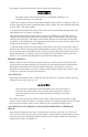
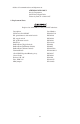
To configure an intercom in the Slave mode, perform the following steps: Disconnect power to the intercom before any installation, maintenance, or configuration changes are performed. 1. Move the J2 jumper on the P.C. board from the MAS to SLA position (see Figure 6). This can be done using long nose pliers, pulling the jumper off the “MAS” and center position and placing it on the “SLA” and center position. 2.
24 Vdc: When connecting the intercom to 24 Vdc, either the positive (+) supply conductor must be fused at the source with a 1/2 A fuse or a power-limited power source must be used. The AD-28X-MV is capable of sending DC power to another unit which is mounted in a remote location without local power. 24 Vdc is available from pins 4 and 5 of the terminal block. It can be run along with the signal lines to an intercom in a remote location.
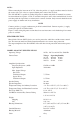
Agency Listings AD-28X-MV UL (UJPX), (UJPX7), (UXPL, Marine) For indoor or outdoor use in Class I, Groups A, B, C and D, Division 2; Class II, Groups F and G, Division 2; Class III hazardous locations; Type 4X enclosure. T-Code at Maximum Ambient Temperature, °C Hazardous Location 40° C 65° C Class I, Division 2, Groups A, B, C, D T6 T5 Class II, Division 2, Groups F, G T6 T5 Class III T6 T5 EXPLOSION HAZARD – SUBSTITUTION OF COMPONENTS MAY IMPAIR SUITABILITY FOR CLASS I, DIVISION 2. B.
The intercom housing has two 1/2”-14 IPS openings in the bottom. When installing the conduit to these openings, seal the threads with pipe compound or other sealing material. For shipboard applications, installations shall be in accordance with the United States Coast Guard, Title 46 CRF, Parts 110‑113. E. Electrical Connections. Do not connect wires when power is applied. All wiring to the intercom is terminated to the terminal block provided.
Address all communications and shipments to: ATKINSON DYNAMICS Service Department 2645 Federal Signal Drive University Park, IL 60484-3167 2. Replacement Parts. Replace fuse with GMC-1/2 only. DO NOT substitute. Description PC Board, AD-28X-MV Kit, potentiometer with on/off switch Kit, toggle switch Kit, push button switch Knob, Pot Rubber Boot (Toggle Switch) Rubber Boot (Pushbutton Switch) Rubber Boot (Volume Control) Terminal Block AD-28X-MV Speaker/Housing Assy.
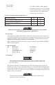
1 A ATKINSON DYNAMICS A FEDERAL SIGNAL COMPANY UNIVERSITY PARK, IL USA 290A4725-01 English A. Push down to talk 2 ATKINSON DYNAMICS A FEDERAL SIGNAL COMPANY UNIVERSITY PARK, IL USA A 290A4725-02 English A.
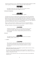
3 A B C (ORANGE) (YELLOW) (BLACK) (GRAY) (BLACK) (BLACK) D (BROWN) BACK VIEW 290A4725-03 English A. Dimple C. Volume control B. Listen/talk toggle switch D. Call push button 4 A 10 B C 9 8 D 7 6 E F 5 4 G H I 3 2 1 L J K 290A4725-04 English A. Terminal block pinout G. Ground B. Dry contact H. 24VDC in/out (+) C. For call I. Neutral D. Audio (-) J. Hot E. Audio (+) K. Earth ground F. Remote control L. 120/240VAC in NOTE: Terminal Block accepts 10 - 22 AWG wire.
5 3.88" (9.9 cm) 5.68" (14.6 cm) ∅ .41 (1 cm) WIDE 2 HOLES 9.88" (25.1 cm) ATKINSON DYNAMICS A FEDERAL SIGNAL COMPANY UNIVERSITY PARK, IL USA A C 2.38" (6.1 cm) 6.50" (16.5 cm) 5.0" (12.7 cm) English A. 1/2-14 pipe thread 2 places B. Audio (Class 2) C. AC input (Class 1) or DC Input/Output (Class 2) Positive supply conductor must be fused at source with 1/2 A fuse or a power-limited source must be used. -9- 4.84" (12.
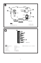
6 2001915 - 02 J1 J5 J2 10 B 9 8 1 BAL UNB J6 O E F G H I 3 2 J4 M D 5 4 J3 N C 7 6 250V J7 MAS SLA 240VAC 120VAC 1/2A A F1 L J K 290A4725-06 English A. Terminal block pinout I. Neutral B. Dry contact J. Hot C. For call K. Earth ground D. Audio (-) L. 120/240VAC‑in E. Audio (+) M. Master slave F. Remote control N. To control panel G. Ground O. Speaker plug H.
-11- WHT GRN AUDIO (+) REMOTE GROUND (-) 24VDC (+) NEUTRAL HOT EARTH GROUND 7 6 5 4 3 2 1 (+) DC POWER COMMON AUDIO AUDIO (-) 8 5 FOR CALL 9 AC 10 DRY CONTACT ATKINSON DYNAMICS 2 3 1WATT 1K BLK WHT GRN ATKINSON DYNAMICS REMOTE B 290A4725-07 3 1 To talk to other stations, press the talk/listen switch and • AD-28X-MV 240V 50/60Hz +DC Power Common BLK WHT -- AD-56-1 -- Remote B 12/24V Models 12/24V Models POWER CONNECTIONS (Remote B): AD-28X-MV AD-28X
-12- REMOTE GROUND (-) 24VDC (+) NEUTRAL HOT EARTH GROUND 6 5 4 3 2 1 WHT 4 2 3 * BLK WHT GRN SEE POWER *CONNECTIONS 1WATT 1K AUDIO (+) 7 BLK AUDIO (-) 8 AC FOR CALL 9 10 DRY CONTACT ATKINSON DYNAMICS ATKINSON DYNAMICS REMOTE B 290A4725-08 WHT TO OTHER INTERCOMS BLK 3 1 AD-28X-MV GRN WHT BLK AD-26A 120/240V Models only 120/240V Models Earth Ground 12/24V Models Neutral 120/240V Models 12/24V Models AD-57A AD-56A AD-27A Common HOT +DC Power POWER CONNEC
-13- ATKINSON DYNAMICS 4 3 5 4 3 GROUND (-) 24VDC (+) NEUTRAL AC 5 6 REMOTE 3 1 1 2 8 290A4725-09 EARTH GROUND HOT NEUTRAL 24VDC (+) GROUND (-) REMOTE AUDIO (+) AC DRY CONTACT AUDIO (-) Slave talks to master hands-free, without having to press a talk • 240V 50/60Hz AD-28X-MV AD-28X-MV AD-28X-MV 120V 50/60Hz 22-30VDC Master Power 4. “Call” Tone Switch 3. Press-to-talk Switch 2. Off/On/Speaker volume control 1.
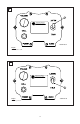
MASTER 10 SLAVE 1 1 2 2 3 ATKINSON DYNAMICS 3 ATKINSON DYNAMICS A FEDERAL SIGNAL COMPANY UNIVERSITY PARK, IL USA A FEDERAL SIGNAL COMPANY UNIVERSITY PARK, IL USA 4 4 DRY CONTACT 10 DRY CONTACT 9 9 DRY CONTACT AUDIO (-) 8 8 AUDIO (-) AUDIO (+) 7 7 AUDIO (+) REMOTE 6 6 REMOTE GROUND (-) 5 5 GROUND (-) 24VDC (+) 4 4 24VDC (+) NEUTRAL 3 3 NEUTRAL 2 HOT 1 EARTH GROUND HOT AC EARTH GROUND 10 DRY CONTACT 1K 1 WATT AC 2 AC FOOT SWITCH N.O. 1 FOOT SWITCH N.O.
-15- AUDIO LINE BLK WHT GRN REMOTE B POWER GRN RED WHT BLK AUDIO CABLE 3 1 1WATT 1K 4 2 AUDIO LINE ATKINSON DYNAMICS REMOTE A GROUND (-) 24VDC (+) NEUTRAL HOT EARTH GROUND 5 4 3 2 1 AC REMOTE 6 AUDIO (-) AUDIO (+) FOR CALL 8 5 7 9 10 DRY CONTACT 3 1 TO OTHER INTERCOMS 290A4725-11 + POWER - POWER AUXILIARY SIGNALING DEVICE -AD-28X-MV AD-28X-MV AD-28X-MV Remote A POWER CONNECTIONS (Remote B): BLK +DC Power HOT WHT Common Neutral GRN Earth Ground 12-18VDC 120V 50/
-16- MASTER B GRN 1 3 1 BLK 3 1 WATT 1K ATKINSON DYNAMICS * BLK * BLK WHT GRN BLK WHT GRN WHT 2 * 2 SEE POWER CONNECTIONS 6 MASTER DESK SET A WHT GRN 7 4 2 CONTROL COMMON AUDIO AC EARTH GROUND 24VDC (+) 4 HOT GROUND (-) 5 NEUTRAL REMOTE 6 1 AUDIO (+) 7 2 AUDIO (-) 8 3 1 3 FOR CALL 9 10 DRY CONTACT BLK 3 WHT 2 GRN 1 ATKINSON DYNAMICS SLAVE 290A4725-12 Reminders: • Before installing remote intercoms, precautions should be taken to prevent feedback between
-17- BLK WHT GRN REMOTE B 2 REMOTE A ATKINSON DYNAMICS COMMON 8 AUDIO 3 BLK WHT GRN WHT BLK * 6 5 4 BLK WHT GRN * WHT BLK ATKINSON DYNAMICS REMOTE C POWER * SEE CONNECTIONS 6 7 4 5 BLK WHT 24VDC (+) NEUTRAL HOT EARTH GROUND 3 2 1 290A4725-13 GROUND (-) 4 AC REMOTE 5 AUDIO (+) 6 4 6 AUDIO (-) 7 FOR CALL 8 9 10 DRY CONTACT ATKINSON DYNAMICS REMOTE D REMOTE A AD-26T AD-27T AD-57T AD-56T REMOTES B & C AD-26 AD-27 AD-57 AD-56 AD-28X-MV AD-28X-MV AD-28X-MV REMOT
blank page