PANEL MOUNT INTERCOMS INSTALLATION AND SERVICE INSTRUCTIONS FOR MODELS AD-26P, AD-27P, AD-56P, and AD-57P Address all communications and shipments to: Electrical Products Division 2645 Federal Signal Drive University Park, IL 60466-3195 (888) 751-1500
INSTALLATION AND SERVICE INSTRUCTIONS FOR ATKINSON DYNAMICS PANEL MOUNT INTERCOMS SAFETY MESSAGE TO INSTALLERS, USERS, AND MAINTENANCE PERSONNEL It is important to follow all instructions shipped with this product. This device is intended to be installed by a trained electrician who is thoroughly familiar with the National Electrical Code and will follow NEC Guidelines as well as local codes.
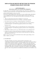
Model AD-26P Model AD-56P Model AD-27P Model AD-57P Supply Voltage 12 VDC 24 VDC 120VAC, 50/60Hz 240 VAC, 50/60Hz Audio Power Output (Max.) 8.0 Watts 11.7 Watts 11.3 Watts 11.3 Watts Power Consumption (Max.) 20.0 Watts 39.6 Watts 28.8 Watts 30.5 Watts Operating Current (Nominal) 1.47A 1.65A 0.240A 0.127A 2 lb. 11.6 oz. 2lb. 11.6 oz. Operating Temperature Shipping Weight Dimensions Ratings -31 F to 150 F ° 2 lb. 1.5 oz. ° 2 lb. 1.5 oz.
CALL BUTTON: “A” Models are equipped with a Call switch. Depressing the call switch transmits an 890 Hz tone to all units in the intercom system. The volume of the call signal is affected by the volume control on the receiving unit, so if volume is turned all the way down at a receiving station, the call signal will not be heard. CAUTION The call signal is louder than normal voice messages being carried on the line. Do not depress the call switch while carrying on a conversation with someone on the system.
D. Mounting. CAUTION The selection of the mounting location for the device, its controls, and the routing of the wiring are to be accomplished under the direction of the facilities and the safety engineer. The panel mount intercom is designed to be mounted behind a customer-supplied panel. 1. Cut an opening and drill the four (4) mounting holes in the customer-supplied panel. Refer to figures 1 and 6. 2. Carefully insert the panel mount intercom into the customer-supplied panel. 3.
2. Replacement Parts. WARNING Replace fuse with GMC-1/2 only. DO NOT substitute.
4.38" -65.90" 6.50" 3.75" 4.67" 3.
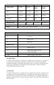
REMOTE SLAVE SPEAKER AD-SF-25/AD-SS-25 2 BLK WHT 6 LOCAL SPEAKER/MICROPHONE MODEL AD-SF-25 "SPK" SPEAKER (WHT/BRN) 200 FT. MAX. "COM" COMMON (WHT) MASTER PANEL MOUNTED INTERCOM 5 3 2 "COM" COMMON (WHT) "REM SPK" REMOTE SPEAKER (BLK) 1K 1WATT 4 1 * - "PWR " (WHT) POWER CONNECTIONS: "PWR+" (Black) +DC-Power "PWR-" (White) Common POWER 12-18VDC 22-30VDC WHT 290A3828-02 "PWR +" (BLK) * BLK SEE POWER CONNECTIONS 12/24V Models 12/24V Models MASTER AD-26-8-M44P AD-56-8-M44P NOTES: 1.
MASTER AD-26CP AD-27CP AD-56CP AD-57CP POWER 12-18VDC 120V 50/60Hz 22-30VDC 240V 50/60Hz -8- SLAVE AD-26DP AD-27DP AD-56DP AD-57DP * "PWR " (WHT) * SEE POWER CONNECTIONS BLK 1WATT WHT "CTRL" CONTROL BLK 1K GRN "AUD" AUDIO "COM" COMMON WHT "COM" COMMON (WHT) GRN "EGND" (GRN/YEL) "PWR " (WHT) - * 3 "PWR +" (BLK) 1 2 4 - "COM" COMMON (WHT) "SPK" SPEAKER (WHT/BRN) 290A3828-03 PANEL MOUNTED INTERCOM SLAVE MODEL AD-SF-25 MODEL AD-SF-25 "SPK" SPEAKER (WHT/BRN) LOCAL SPEAKER/MICROPHO
-9- Operating Principle: • Master normally listens to Slave. • Slave talks to Master "hands-free", without having to press a talk switch. • To talk into Master, press talk switch and speak into speaker/microphone. Release talk switch to listen. NOTES: 1. Mounting Holes 2. Cover Plate 3. Off/On/Speaker Volume Control 4. Press-to-Talk Switch 5. Use shielded audio cable in electrically noisy areas. Ground one end of the shield to "earth" ground.
Earth Ground MASTER AD-26P AD-27P AD-56P AD-57P "EGND" (Green/yellow) POWER 12-18VDC 120V 50/60Hz 22-30VDC 240V 50/60Hz -10- Operating Principle: • When one talks, all intercoms will hear. • To talk to other stations, press the talk/listen switch and speak into the speaker/microphone. • Release talk/listen switch to listen.
3.60" PANEL-MOUNT-TEMPLATE 3.75" 4 x ø0.191" 5.90" 5.60" 6 290A3828-07 2561542D REV. D 2/01 Printed in U.S.A.