Atkinson Dynamics Intercoms Model AD26-Z Installation and Service Instructions Address all communications and shipments to: 2645 Federal Signal Drive University Park, IL 60466-3195 (800) 264-3578 2561733C REV. C 1008 Printed in U.S.A.
INSTALLATION AND SERVICE INSTRUCTIONS FOR ATKINSON DYNAMICS HEAVY-DUTY INTERCOMS WARNING The lives of people depend on your safe servicing of these products. It is important to read and follow all instructions shipped with the products. In addition, listed below are some other safety instructions and precautions you should follow: • Read and understand all instructions in this manual before servicing this intercom.
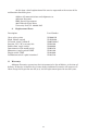
Basic Model AD26-Z Specifications: Supply Voltage Current Draw Amplifier Specifications Frequency Response (-6dB) Input Impedance Max. Output Voltage: Sine Wave: Unbalanced Output Square Wave: Unbalanced Output 12 Vdc-24 Vdc 1.47 A max. at 13.6VDC, 100 mA standby 320 Hz to 8.0 kHz 10,000 ohms 7.9 Vrms 9.
MASTER UNITS: “C” Models default to Master, or speaker, mode. In Master mode, the unit acts as a speaker and broadcasts audio signals generated elsewhere in the intercom system. Depressing the Talk switch turns the unit into a microphone and enables the user to broadcast to all other intercoms in the system. Releasing the switch returns the unit to Master mode. Figure 2, 3, and 6 illustrates a Master/Hands-Free intercom system. HANDS-FREE UNITS: “D” Models default to Hands-Free, or microphone, mode.
with the “-M44” option. The volume control for these speakers is located on the intercom. Model ADSS-25-Z has a swivel-mounting bracket, while Model ADSF-25-Z has holes in its outer flange for flush mounting. All speakers are rated for 25 watts. Speaker Specifications ADSV-25-Z ADSS-25-Z ADSF-25-Z Frequency Response (Hz) 800 – 5,000 800 – 5,000 800 – 5,000 Power Handling (Watts) 25 25 25 Shipping Weight (lb.) 10.0 6.0 9.0 Dimensions (inches) 10.0 x 6.4 x 4.4 (H x W x D) 6.4 x 5.1 (Dia.
Model ADSF-25-Z Mounting: Speaker Model ADSF-25-Z is intended for flush mounting. Figure 10 is a dimensional outline drawing of the speaker. There are six mounting holes approximately 0.200” in diameter in its outer flange. Install the speaker behind a 6-1/8” diameter hole. Hardware for mounting the speaker shall be provided by the installer.
At this time a brief explanation of the service requested or the nature of the malfunction should be given. 2. Address all communications and shipments to: Atkinson Dynamics EMP Service Department 2645 Federal Signal Drive University Park, IL 60466-3195 Replacement Parts.
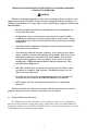
1 REMOTE A REMOTE B 1 22 1 22 3 BLK WHT AUDIO CABLE 3 BLK WHT BLK AUDIO CABLE BLK TO OTHER INTERCOMS AUDIO LINE WHT Operating Principle: • When one talks, all intercoms will hear. • To talk to other stations, press the talk/listen switch and speak into the speaker/microphone. Release talk switch to listen. WHT 290A4467-01 NOTES: 1. Speaker/Microphone 2. Off/On/Speaker Volume Control 3.
-8WHT 2 BLK 3 CONTROL GRN 1 BLK WHT COMMON 1 WATT 1K 2 2 BLK BLK WHT 3 WHT 5 2 2 AUDIO 4 1 GRN 3 1 MASTER "B" BLK 3 Power 12–24 Vdc Master A Master B AD26C-7-Z AD26C-Z Hands-Free AD-26D-Z POWER CONNECTIONS: BLK +DC Power 12/24V Models WHT –DC Power 12/24V Models 290A4467-02 WHT 2 GRN 1 HANDS-FREE Before installing remote intercoms, precautions should be taken to prevent feedback between two or more remotes in close proximity and acoustically reflective areas.
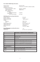
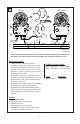
3 MASTER HANDS-FREE 6 5 1 A 2 3 5 4 A 1K BLK WHT GRN BLK WHT 1 WATT AUDIO CONTROL COMMON BLK WHT GRN BLK WHT TO OTHER INTERCOMS 290A4467-03 Before installing remote intercoms, precautions should be taken to prevent feedback between two or more remotes in close proximity and acoustically reflective areas. Operating Principle: • When one talks, all remotes will hear. • To talk into remote, press talk switch and talk into speaker/microphone. Release talk switch to listen.
4 NOTES 1. Speaker/Microphone 2. Off/On Speaker Volume Control 3. Talk/Listen Switch 4. Remote Hands-Free Station Model ADSV-25-Z 5. 16–20 gauge low voltage audio cable. Shielded twisted pair may improve performance. 6. Shielded audio cable would improve performance when operating in high electromagnetic fields. Ground one end of the shield to earth ground.
SPEAKER 5 5 BLK 1 WHT 2 MASTER 1 200 FT. MAX. 2 3 AUDIO COMMON 1K 4 BLK BLK WHT 1WATT WHT 290A4467-05 Operating Principle: • Hands-Free station is both a speaker and a microphone. • Master is normally in “Listen” mode until the talk button is pressed to talk to remote. • Outgoing and incoming volumes are controlled by separate controls on master. NOTES: 1. Speaker/Microphone 2. Off/On/Speaker volume control 3. Talk/Listen switch 4. Outgoing Volume Control 5.
2 -12- (-) POWER (+) MASTER "A" POWER 12-24VDC MASTER A AD26C-1-Z MASTER B AD26C-1-2-Z BRN RED N/C AUDIO COMMON WHT RED HANDS-FREE AD26D-1-Z RED N/C 290A4467-06 BRN BRN 4 WHT BLK BLU GRN HANDS-FREE WHT BLK CONTROL - DC POWER BLK BLU + DC POWER GRN BLU 1WATT 1K 3 AUDIO 5 2 2 1 GRN 3 1 MASTER "B" NOTES: 1. Speaker/Microphone 2. Off/On/Speaker Volume Control 3. Press-to-Talk Switch 4. Red wire connected in “-2” model only. External Press-ToTalk switch, momentary (e.g.
7 2 BLK WHT 1 "SPK" SPEAKER (WHT/BRN) 200 FT. MAX. "COM" COMMON (WHT) 3 5 "REM SPK" REMOTE SPEAKER (BLK) "COM" COMMON (WHT) 6 4 BLK BLK WHT WHT 290A4467-07 POWER CONNECTIONS: BLK +DC Power 12/24 V Models WHT –DC Power 12/24 V Models NOTES: 1. Speaker/Microphone Model ADSF-25-Z 2. Remote Speaker Model ADSS-25-Z 3. Panel Mount Intercom Model AD26-8-M44P-Z 5. Off/On/Speaker Volume Control 4. Remote Speaker Volume 6. Talk/Listen Switch 7. 16–20 gauge low voltage audio cable.
-14- MASTER AD26CP-Z "PWR -" (WHT) "PWR +" (BLK) AD26CP-Z 3 REMOTE A PANEL MOUNTED MASTER INTERCOM "AUD" AUDIO "COM" COMMON WHT 1K 1WATT WHT GRN BLK "COM" COMMON (WHT) 290A4467-08 AD26DP-Z POWER CONNECTIONS: BLK +DC Power 12/24 V Models WHT –DC Power 12/24 V Models "CNTL" CONTROL "PWR -" (WHT) "PWR +" (BLK) 3 GRN 5 1 2 4 LOCAL SPEAKER/MICROPHONE MODEL ADSF-25-Z "SPK" SPEAKER (WHT/BRN) REMOTE B PANEL MOUNTED HANDS-FREE INTERCOM BLK HANDS-FREE AD26DP-Z "COM" COMMON (WHT) "SPK" S
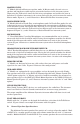
1/2-14 NPT (2 PLACES) 5.03 3.88 2.37 0.41 DETAIL "A" 0.51 R0.20 -156.70 UNIVERSITY PARK, IL USA A FEDERAL SIGNAL COMPANY ATKINSON DYNAMICS 5.68 9.90 290A4467-09 4.
10 5.0 4.1 (W/O COVER) Ø7.25 Ø.22 (6 PLCS.) ON A Ø6.63 B.C.
11 5.05 4.14 (W/OUT COVER) 8.40 Ø6.25 4.94 SEE DETAIL "A" Ø.28 (3 PLCS.) 1.75 2.63 2.00 2.
4.38" -185.90" 6.50" 3.75" 4.67" 3.
GREEN AUDIO N/C BLUE POWER(+) BLACK CONTROL WHITE POWER(-) N/C SLAVE UNIT AD26D-1-ALT3 BLACK POWER(+) PN 1751240 4 5 6 WHITE CONTROL PLUG N/C 4 5 6 3 2 1 RED POWER(+) WHITE CONTROL PLUG N/C LEFT SIDE CABLE 1751247 SHOWN FROM CABLE ENTRY END BLACK POWER(-) GREEN AUDIO PLUG N/C SLAVE UNIT AD26D-1-ALT4 1 SHIELD POWER(-) 5 4 GREEN AUDIO BLACK POWER(-) 3 2 RED POWER(+) WHITE CONTROL A E B D C N/C RED CONTROL WHITE POWER(-) E B D C A RED CONTROL WHITE POWER(-) SINGLE C