All-In-Wonder® X1900 Series Installation and Setup User’s Guide P/N 137-71028-10
ii Copyright © 2005, ATI Technologies Inc. All rights reserved. ATI, the ATI logo, and ATI product and product-feature names are trademarks and/or registered trademarks of ATI Technologies Inc. All other company and/or product names are trademarks and/or registered trademarks of their respective owners. Features, performance and specifications are subject to change without notice. Product may not be exactly as shown in diagrams.
iii L IMPORTANT SAFETY INSTRUCTIONS • • • • • • • • • • • Read Instructions - All the safety and operating instructions should be read before the product is operated. Retain Instructions - The safety and operating instructions should be retained for future reference. Heed Warnings - All warnings on the product and the operating instructions should be adhered to.
iv
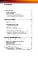
v Contents Getting Started . . . . . . . . . . . . . . . . . . . . . . . . . . . . 1 System Requirements Before You Begin Record Your Serial and Part Numbers Update Your PCI Express® Chipset Drivers Uninstall Previous Graphics Card Drivers 2 2 2 3 4 Installing Hardware . . . . . . . . . . . . . . . . . . . . . . . . .
vi Other Quick Launch Access Points Displays Manager Video Display Options Color Monitor Properties Component Video Properties Digital Panel Properties Hotkeys Manager ATI Overdrive 3 Profiles Manager Preferences Help 22 23 23 24 25 25 25 26 26 26 27 27 27 28 28 Using TV Display and Capture Features . . . . . . .
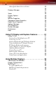
vii Reference . . . . . . . . . . . . . . . . . . . . . . . . . . . . . . . . 41 Troubleshooting Product Registration Customer Care Getting Additional Accessories Compliance Information FCC Compliance Information Industry Canada Compliance Statement CE Compliance Information Informations de conformité de la CE Electrical Safety Waste Electrical and Electronic Equipment (WEEE) Directive Compliance 41 43 43 45 45 45 46 46 46 46 47 Index . . . . . . . . . . . . . . . . . . . . . . . . . . . . . . . . . . .
viii
1 CHAPTER 1: Getting Started The All-in-Wonder® X1900 Series graphics cards add TV, Personal Video Recording (PVR), and powerful video acceleration to your PC. You can use your All-in-Wonder® X1900 Series card to connect your computer to a television for playing games, giving presentations, watching movies, and browsing the Internet. Several software features are included with your All-in-Wonder® X1900 to enhance your television experience.
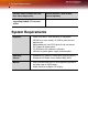
2 System Requirements Personal video recorder with realtime video compression Remote Wonder™ USB remote control (optional) AC-3 digital audio playback supporting Dolby® 5.
Before You Begin 3 Before You Begin Before you begin installing your new All-in-Wonder® X1900 Series graphics card, please do the following. Record Your Serial and Part Numbers The serial number and 102 part number printed on the graphics card are required for registration. They are located on a sticker on the back of the card. X Serial number (S/N) Y 102 part number (P/N) Write the numbers, shown in bold above, down before installing your new ATI product.
4 Before You Begin Determining the motherboard chipset 1 Open the Control Panel from the Start Menu and select System; in Windows® XP’s Category View, System can be found under Performance and Maintenance. 2 In the System Properties dialog, select the Hardware tab. 3 Select Device Manager. 4 From the Device Manager tree view, expand the System Devices branch. 5 Scroll through the list of system devices until you find a listing for the PCI Express controller.
Before You Begin 5 Uninstall Previous Graphics Card Drivers To ensure the successful installation of your new All-in-Wonder® X1900 card, you must uninstall the drivers for the existing graphics card before removing it from your computer. To uninstall previous drivers With your current graphics card still in your computer: 1 Close all applications that are currently running. 2 Navigate to the Control Panel and select Add/Remove Programs.
6 Before You Begin
Quick Installation 7 CHAPTER 2: Installing Hardware This chapter will guide you through the physical installation of your new Allin-Wonder® X1900 Series graphics card. Quick Installation For experienced users and system administrators, follow these brief instructions for installing your All-in-Wonder® X1900 card in the shortest possible time. Quick Installation Steps 1 Uninstall the drivers and software for your old graphics card.
8 Detailed Installation Detailed Installation The following instructions will take you step by step through the installation of your new All-in-Wonder® X1900. n All-in-Wonder® X1900 Graphics Card Installing the All-in-Wonder® X1900 Series graphics card 1 Turn off the computer, monitor, and other peripheral devices. 2 Unplug the computer’s power cord and disconnect all cables from the back of your computer.
Connecting Additional Power 9 3 Remove the computer cover. If necessary, consult your computer’s manual for help in removing the cover. L 4 WARNING - Remember to discharge your body’s static electricity by touching the power supply or the metal surface of the computer chassis. Unscrew or unfasten and remove any existing graphics card from your computer. Note: If your computer has an on-board graphics capability, you may need to disable it on the motherboard.
10 Connecting Additional Power Note: All-in-Wonder® X1900 Series graphics cards that require connection to the computer’s power supply will have a power cable connected to them. L Consult your system builder or OEM to ensure that your system has an adequate power supply. A PCI Express® compatible system has a specialized 12V graphics card power connector. A 450 watt or greater power supply is recommended.
Connecting Additional Power 11 6 Power connector to Power Supply Connecting Display Devices The following connections are available: • VGA — for standard VGA monitors. • DVI-I — for digital flat-panel displays. You can connect an analog CRT display using an optional DVI-I-to-VGA adapter, as shown.
12 Input and Output Adapters Turning on the System L WARNING - Turn on your monitor before you turn on your computer. Failure to do so could damage your monitor. If you have properly installed your graphics card, operating system messages will appear once the boot procedure is finished. Your monitor will be running in a basic video mode. Higher refresh rates are not available at this stage of the installation.
Input and Output Adapters 13 1 Typical VCR or camcorder audio and video output connectors. Use composite video out or S-Video out. 2 Cable with S-Video plug at each end. 3 Cables with RCA plug at each end, available separately from a consumer electronics dealer. 4 ATI Input Adapter. 5 Input / Output connector. 6 All-in-Wonder® X1900 card. Watching PC Output on a TV and Recording on a VCR Use the ATI output adapter to connect a TV, camcorder, or VCR to your Allin-Wonder® X1900 card, as shown.
14 Input and Output Adapters RF1 Cable TV connection - Analog (and DVB-T where available). RF2 Cable FM Radio connection. 1 Typical VCR or camcorder audio and video input connectors. Use composite video in or S-Video in; S-Video will provide better results. To use your TV as a display, you must enable TV Out . 2 Cables with RCA plug at each end, available separately from a consumer electronics dealer. 3 Cable with S-Video plug at each end. 4 ATI Output Adapter.
Input and Output Adapters 15 8 Line-In to sound card 9 Dolby® Digital AC-3 Amplifier. Watching your PC Output on High-definition TV Use the ATI output adapter to connect a high definition TV (North America only) to your All-in-Wonder® X1900 card, as shown. 1 Input / Output Adapter. 2 All-in-Wonder® X1900 card. 3 ATI HD Output Adapter. 4 Cables with RCA plug at each end, available separately from a consumer electronics dealer.
16 Input and Output Adapters 5 Typical HDTV video inputs. Note: Input and output cable lengths should not exceed 50 feet (15m). Y = Green Pb = Blue Pr = Red 6 Cable with mini-stereo plug at each end, available separately from a consumer electronics dealer, for connecting PC speakers (optional). 7 LINE IN to sound card 8 Dolby® Digital AC-3 Amplifier. 9 Cable with RCA plug at each end, available separately from a consumer electronics dealer.
Input and Output Adapters 17 1 ATI input adapter used with earlier All-in-Wonder® products. 2 RF1 F-connector for cable TV input. 3 RF2 F-connector for cable FM radio input. 4 ATI input connector used with earlier All-in-Wonder® products. 5 S-Vide connector 6 Input / Output connector. 7 All-in-Wonder® X1900 card.
18 Input and Output Adapters Using the SCART Connector SCART is an acronym for “Syndicat des Constructeurs d'Appareils Radiorécepteurs et Téléviseurs”. SCART is an analog 21-pin connector used mainly in Europe for transferring audio and video signals between VCRs, DVD players, personal computers, and set-top boxes. It is sometimes referred to as Péritel or the Euroconnector. Your All-in-Wonder® X1900 comes with a SCART adaptor for connecting to compatible equipment as shown. 1 All-in-Wonder® X1900 card.
Input and Output Adapters 19 4 SCART compatible TV, VCR, Camcorder 5 PC sound card 6 Cable with mini-stereo plug at each end, available separately from a consumer electronics dealer, for connecting PC speakers (optional).
20 Input and Output Adapters
Installing Drivers and Software in Windows® 19 CHAPTER 3: Installing Software and Drivers This chapter will guide you through the installation of the drivers and software associated with your All-in-Wonder® X1900 graphics card. Installing Drivers and Software in Windows® You will need to install the All-in-Wonder® X1900 drivers and software in the following cases: • After you have installed the card in your system. • After you have reinstalled or upgraded your operating system.
20 HydraVision™ Multi-monitor Management 2 Run the ATISETUP utility. The ATISETUP utility will start automatically if you insert the ATI Installation CD-ROM into your CDROM drive after the operating system has started. If your CD-ROM auto-run is not enabled or the ATISETUP utility does not start automatically: a) Click the Start button in the task bar. b) Click Run. c) Select ATISETUP.EXE from the root directory of the ATI Installation CD-ROM. d) Click OK. 3 Click Install under Software Install.
Monitor Configuration 21 For more information consult the HydraVision™ user’s guide included on the ATI Installation CD-ROM. Monitor Configuration Once the drivers and software have been installed, you can configure your monitor.. L Warning - Choosing a refresh rate unsupported by your monitor may damage your monitor. Consult your monitor’s documentation if necessary.
22 Starting the ATI Multimedia Center 3 Browse to ATISETUP.EXE on the root directory of the ATI Installation CD-ROM. 4 Click OK. Starting the ATI Multimedia Center After you have run the ATISETUP utility and you have retarted your system, The ATI Multimedia Center™ Launchpad opens on your desktop automatically. The Launchpad provides a convenient way to start all your Multimedia Center features — just click the one you want.
Launching Catalyst™ Control Center 23 CHAPTER 4: Catalyst™ Control Center The Catalyst™ Control Center is a graphical user application providing access to the display features contained within the installed ATI hardware and software. Use the Catalyst™ Control Center to fine-tune your graphics settings, enable or disable connected display devices, and change the orientation of your desktop. Many of the features show you a preview of the changes before they are applied.
24 Launching Catalyst™ Control Center Launching Catalyst™ Control Center Using the Start Menu From the windows task bar, click the Start button: • For Windows® XP, point to All Programs > ATI Catalyst™ Control Center. Other Quick Launch Access Points Launching Catalyst™ Control Center from ATI Multimedia Center™ You can also access the Catalyst™ Control Center while an ATI Multimedia Center™ application, like TV Player, is running.
25 Catalyst™ Control Center Dialog Displays Manager The Displays Manager aspect is the central location for configuring your display devices and arranging your desktop. Use the Displays Manager aspect to quickly change your display setup, arrange your desktop in a multi-monitor environment, and enable TV Out. Those new to the Catalyst™ Control Center may use the Basic View wizard to help you configure your display preferences.
26 Catalyst™ Control Center: Standard View
Video 27 Catalyst™ Control Center: Advanced View Video Use the Video aspect to use preconfigured profiles that best match your viewing environment. Switch to the Advanced view to manually adjust video overlay and choose a preferred viewing mode, such as Widescreen or Fullscreen modes. To access the Video aspect • Select Video in either Basic or Advanced View. Display Options The Display Options aspect gives you additional control to optimize performance of OpenGL® and Direct 3D® applications.
28 Color Choose one of the Display Detection Options to prevent screen flicker when detecting a display. If you are using an older TV or one that has non-standard inputs that may not be automatically detected, use Force TV Detection. When a TV is detected using this method, it appears in the Displays Manager aspect and can be configured as required. However, some features that rely on automatic detection, such as extended desktop, will not be supported.
Digital Panel Properties 29 Component Video Properties The Component Video Properties aspect of the Catalyst™ Control Center adds further support when using the ATI HDTV Component Video Adapter. Component Video Properties is made up of: • Formats • Adjustments • Advanced Digital Panel Properties Use the Digital Panel Properties aspect to configure the DVI settings and Image Scaling to improve image quality without impacting performance.
30 ATI Overdrive 3 ATI Overdrive 3 Use the ATI Overdrive 3 aspect to maximize the performance of the graphics processing unit (GPU) on your graphics card. An on-chip thermal sensor constantly monitors the temperature of the GPU allowing the maximum clock speed to be maintained while avoiding overheating. If the GPU gets too hot, the ATI Overdrive 3 aspect will automatically decrease the clock speed until a safe temperature is reached.
Preferences 31 To access the Profiles Manager • Click the Profiles button in Advanced View of the Catalyst™ Control Center. Preferences Use the Preferences page to restore factory defaults, change skins, or enable/ disable the System Tray icon.
32 Help
Using TV Out 33 CHAPTER 5: Using TV Display and Capture Features Using TV Out Your All-in-Wonder® X1900 has TV Out capability. It also supports YPbPr component video output. For European customers, SCART-out is supported and included on the Input/Output connector. Viewing Your PC’s Display on a TV You can attach your graphics card to a TV and monitor at the same time. You can also connect it to your VCR and record your monitor’s display.
34 Using TV Out During start up, your All-in-Wonder® X1900 will go through a sequence of mode settings, during which your TV display will remain blank. This process takes only a few seconds and programs the TV display. To enable or disable the TV display 1 Access the Windows® Control Panel. Double-click Display. 2 Click the Settings tab and then the Advanced button. 3 Click the ATI Displays tab. Click the TV button. 4 Click the enable button 5 Click OK or Apply to save the changes.
Using TV Out 35 caused by the changes your All-in-Wonder® X1900 makes in order to render your desktop display on a TV screen. Use the controls available on the Adjustments tab on the Monitor Properties page (accessible by clicking on the Monitor button on the ATI Displays tab) to adjust the display on your monitor only. Click the TV button to adjust the TV display only. Viewing Text on a TV A TV is designed primarily to show moving images. The large dot pitch of a TV will yield poor quality static images.
36 Using TV Out
Connecting Your Monitors 33 CHAPTER 5: Using Multiple Displays This chapter describes how to attach multiple monitors to your All-inWonder® X1900 card, as well as the allowable multi-display configurations. Connecting Your Monitors Your All-in-Wonder® X1900 provides hardware support for one DVI-I monitor or two VGA monitors using the optional DVI-I-to-VGA adapter. A TV can also be used to expand your desktop by using the S-Video out.
34 Connecting Your Monitors Connections and Adapters for the All-in-Wonder® X1900 Card X Standard VGA Monitor Connector. To connect a VGA monitor to the DVI-I connector, plug the supplied DVI-I-to-VGA adapter into the DVI-I connector, then plug your monitor cable into the adapter. Y DVI-I-to-VGA Adapter (if necessary). Z DVI-I Backplate Connection. To connect a flat panel, plug the monitor’s DVI-I connector directly into the DVI-I connection.
Connecting Your Monitors 35 To connect your monitors 1 Turn off your computer and monitors. 2 Plug the monitor cables into their appropriate connectors. 3 Turn on your monitors first, and then restart your computer so that Windows® can detect the new hardware settings. 4 When the New Hardware Found Wizard appears, at the appropriate prompt insert the ATI Installation CD to load the drivers for your All-inWonder® X1900 card.
36 Display Configurations Display Configurations Your All-in-Wonder® X1900 graphics card provides dual display functionality and TV Out. The following table lists the different ways you can connect displays to your card. Display Configuration Connector(s) Used Comments Single CRT display VGA connector OR DVI-I connector with DVI-I-to-VGA adapter CRT- cathode ray tube analog display. Single DFP display DVI-I connector DFP - digital flat panel display.
MulTView™ 37 Display Configuration Connector(s) Used Comments CRT display + DFP display + TV VGA connector + DVI-I connector + S-Video Out The TV display will “clone” the image of one of the other two displays CRT display + DFP display + HDTV VGA connector + DVI-I connector + HDTV (YPrPb) output cable UNSUPPORTED CONFIGURATION CRT display + CRT display + TV VGA connector + DVI-I connector with DVI-I-to-VGA adapter + S-Video Out CRT display + CRT display + HDTV VGA connector + DVI-I connector wi
38 MulTView™ • Picture in Picture (PiP): When the main video window is in fullscreen, the MulTView™ PiP video window is embedded in the main window. It can be positioned in the top/bottom left or top/bottom right of the main window. • Picture outside Picture (PoP): If you use only one monitor, the main and MulTView™ video windows can be displayed in separate windows. If you use dual monitors, you can drag the MulTView™ window to the secondary monitor.
MulTView™ 39 black. For example when the borders are red, a Remote Wonder™ channelchange command will change the MulTView™ channel. MulTView™ Audio Requirements If you have one audio card or an integrated audio chip, you must connect one audio path internally (CD-In, for example) and the other externally (Line-In, for example). If you have two audio cards or one audio card and an integrated audio chip, you can connect both audio paths internally, externally, or one internally and the other externally.
40 MulTView™
Troubleshooting 39 CHAPTER 6: Reference This chapter provides information on troubleshooting, where to get additional accessories, how to register your product, plus warranty and compliance information. Troubleshooting The following troubleshooting tips may help if you experience problems. ATI’s documentation contains helpful installation/configuration tips and other valuable feature information. Please contact your dealer for more advanced troubleshooting information.
40 Troubleshooting General Troubleshooting Problem Possible Solution No Display • • • • • Screen Defects Appear • • Check that the card is seated properly in its expansion slot. Ensure that the monitor cable is securely fastened to the card. Make sure that the monitor and computer are plugged in and receiving power. If necessary, disable any built-in graphics capabilities on your mother board. For more information, consult your computer’s manual or manufacturer.
Product Registration 41 General Troubleshooting Problem Possible Solution Operating System Warns that Video Card Isn’t Properly Configured • • Check the driver installation and make sure that all software is correctly loaded corresponding to your operating system and applications. Re-install the ATI drivers for your All-in-Wonder® X1900 card.
42 Customer Care Customer Care For detailed instructions on how to use your ATI product, refer to the Online User’s Guide included on your ATI installation CD-ROM. If you require further assistance with your product, the following Customer Care options are available: Service Availability Language Access Online 24/7 English, French, Spanish, Portuguese, German ati.com English 1-877-284-1566 (toll-free) or Mail Telephone US & Canada 9:00AM 7:00PM EST. Monday to Friday. or ATI TECHNOLOGIES INC.
Getting Additional Accessories 43 ATI Customer Care will work to resolve your issue and help you to get your ATI product up and running. If your issue is not resolved, our technicians will determine whether the difficulty you are experiencing is the result of the ATI product, whether your product contains a defect, and whether your product is under warranty. • ATI Customer Care is unable to assist with refunds, returns, or exchange specific inquiries.
44 FCC Compliance Information FCC Compliance Information This All-in-Wonder® X1900 Series product complies with FCC Rules part 15. Operation is subject to the following two conditions • This device may not cause harmful interference, and • This device must accept any interference received, including interference that may cause undesired operation. This equipment has been tested and found to comply with the limits for a Class B digital device, pursuant to Part 15 of the FCC Rules.
FCC Compliance Information 45 CE Compliance Information EMC Directive 89/336/EEC and amendments 91/263/EEC, 92/31/EEC and 93/68/EEC, Class B Digital Device EN 55022:2003/CISPR 22 Class B, Limits and Methods of Measurement of Radio Interference Characteristics Information Technology Equipment.
46 FCC Compliance Information
49 Index Numerics 102 part number 3D 25, 27 480i 43 480p 43 720p 43 A accessories 45 adapters 2 compatibility with earlier products input and output 10 13 Advanced View 25 ATI Overdrive 3 27 ATISETUP utility 19 B brightness 25, 42 C Catalyst Control Center 21, 27, 28 Cathode Ray Tube (CRT) 26 Color 19, 25, 42 Compliance Information 45 compliance information 41 Component Video Properties 26 configuration primary monitor 19 configuration tips 41 contrast 25, 33, 42 TV display 33 Control Panel 4, Cop
50 Direct 3D 25 Display Configurations 39 display configurations 37, 39 Display Data Channel (DDC) 26 Display Detection Options 25 Display devices 8 connecting display devices multiple 35 Display Options 25 displaying PC output on HDTV 12 displaying PC output on TV 11 Dot pitch 33 dot pitch 33 driver installation 17 drivers installing 17 uninstalling 4 DVI 26 DVI-I 42 E EazyLook ™ 40 Extended Display Identification Data (EDID) 26 F FCC Compliance 45 Fullscreen 25 Fullscreen modes 25 G games TV displa
51 I Industry Canada Compliance input and output adapters 10 input/output adapter 13 Installation detailed 46 6 installation tips 41 M Multimedia Center starting 20 multi-monitor 23 multiple displays MulTView ™ 38 35 audio requirements 40 Picture in Picture, Picture outside Picture TV Wonder ™ 38 O OpenGL 25 P PCIe drivers chipset drivers 3 Picture in Picture 38 Picture outside Picture 38 Preferences 28 Product Registration 43 profiles 27 Profiles Manager 27 R recording PC output on videotape 11
52 T Troubleshooting 41, 43 43 troubleshooting 41 TV 23, 25, 31, 32, 33, 43 MulTView ™ 38 TV display 31, 33 contrast 33 games 33 hardware restrictions 32 horizontal size 33 TV Out 31, 32 TV Wonder ™ 38 HDTV adapter V Video 25, 26, 42, 43 W Warranty 44 warranty 41 Waste Electrical and Electronic Equipment (WEEE) Compliance watch movies on PC record video from VCR or camcorder Widescreen mode 25 Windows 19, 43 Windows Advanced Options Menu Windows XP 41 Y YPbPr 43 10 41 47