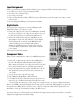
ATP 8500 DIGITAL PREAMPLIFIER-PROCESSOR OWNER’S GUIDE ATI Amplifier Technologies
This product is manufactured under license from Dolby Laboratories Licensing Corporation. “Dolby”, the Double-D symbol, “Dolby Digital” and “Pro Logic” are trademarks of Dolby Laboratories Licensing Corporation. DTS is a trademark of Digital Theatre Systems, Inc.
▼ INTRODUCTION Functional Description ........................ Page 4 Software Version ................................. Page 4 Unpacking .......................................... Page 4 Safety Instructions .............................. Page 5 Rack Mounting ................................... Page 5 QUICK SET-UP GUIDE Connections ....................................... Page 6 Input Assignment ............................... Page 7 Digital Audio ......................................
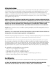
Introduction Functional Description Thank you for selecting ATI’s ATP 8500 Digital Preamplifier-Processor for your audio and video home theater. The ATP 8500 is the center of a high-end cinema and audio system. The ATP 8500 decodes Dolby Digital, DTS and Dolby Pro Logic. Naturally, the ATP 8500 can also function as a High-End stereo preamplifier, and the digital signal processing and conversion can be bypassed. The 7.1 channel input is provided with comprehensive volume control facilities.
Safety Instructions NOTE FOR INSTALLATION: The ATP 8500 generates a certain amount of heat and requires ventilation. Do not place it on a soft surface such as a rug into which it could sink. You should also avoid a built-in installation place such as a bookcase or a rack unless you can provide proper ventilation for ATP 8500. Do not use this unit near water: for example, near a bathtub, washbowl, kitchen sink, laundry tub, in a wet basement, or near a swimming pool.
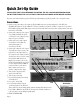
Quick Set-Up Guide PLEASE NOTE: WHEN USING THE REMOTE TO CONTROL THE ATP 8500 PREAMPLIFIER-PROCESSOR, YOU MUST FIRST PRESS THE “AVC” BUTTON IN THE UPPER LEFT CORNER OF THE REMOTE CONTROL . If you just can’t wait and want to get the ATP 8500 up and running as quickly as possible, here’s the quickest way: Connections 1. Connect your power amp to the outputs (gold plated RCA connectors on upper right side) of the ATP 8500. The RR & LR outputs are for the additional 7.1 mode.
Input Assignment Want to get a little more sophisticated? Then add these steps to assign your VCR to a front panel input button: 1. Go to Menu, go to Source setup, select input title VCR 1. 2. Go to video, select composite video 1. 3. Go to audio, select audio 1. 4. Back out of the Menu by scrolling to EXIT (do not press the Exit button on the front panel or the remote control), and press enter. You’ve now assigned the VCR input to front panel button VCR 1.
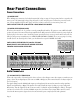
Rear Panel Connections Power Connections (1) POWER INLET Before making any connections, check that the mains (AC) voltage or range of voltages printed on the rear panel is the same as your local mains supply voltage. Plug the female (socket) end of the power cord into the power inlet on the rear of the preamplifier. Plug the male (plug) end of the cord into a wall socket or an extension power cord. NOTE: CONNECT THE ATP 8500 ONLY TO A GROUNDED WALL SOCKET.
(4) TAPE INPUT/OUTPUT These connectors are for all types of tape recorders, including 3-head types, which allow you to monitor the signal from the tape at the same time it is being recorded. Connect a stereo cable pair from the TAPE REC output sockets of the preamp to the LINE IN or RECORD IN sockets of your tape recorder. Connect a second pair of stereo cables from the TAPE PLAY input sockets to the LINE OUT or PLAY OUT sockets of your tape recorder.
Video Connections (9) COMPOSITE VIDEO INPUTS 1 THROUGH 6 These are the default video inputs. Connect the composite video output cables coming from your video sources to these inputs. Note: Take care to use inputs with the same name for the composite video, S-Video and analog audio cables from a single source. E.g. cables from a VCR (VideoCassette Recorder) should go to the VCR-VIDEO, VCR COMPOSITE VIDEO and VCR ANALOG inputs.
9 10 11 12 13 14 15 16 17 18 19 20 21 22 23 Digital Audio Connections (17) COAXIAL DIGITAL AUDIO INPUTS 1 THROUGH 4 Connect the coaxial digital output cables from your source devices to these inputs. You can freely associate the digital inputs to any source (see menu option for further reference). (18) OPTICAL DIGITAL AUDIO INPUTS 1 & 2 These connections require optical cables and connectors. You can freely associate the optical inputs to any audio source (see menu option for further reference).
Front Panel Controls POWER (STANDBY) SWITCH ON FRONT PANEL When you plug the ATP 8500 into a “live” mains power wall socket and turn the rear panel POWER switch ON, it will power up in “standby” mode. In this mode the internal circuit of the ATP 8500 is powered but inactive.
SOURCE SELECT ▲ AND ▼ (UP AND DOWN) With these buttons you can browse up or down through the inputs to select the source (audio or audio-video) that is fed to the main outputs. The signal you have selected will also be fed to the TAPE REC output sockets for recording. The display shows the input you have selected. The SOURCE ▲ and ▼ buttons browse through all the sources except TAPE. You can select the 7.1 CHANNEL and TAPE inputs by the TAPE MONITOR and 7.1 CHANNEL input buttons.
HEADPHONE VOLUME DOWN/UP AND HEADPHONE INPUT The up and down buttons control the headphone volume independently of the main volume. When adjusting the headphone volume, the OSD shows the relative difference (volume offset) compared to the main volume. It does not show the absolute level. All speakers will be turned off when a set of headphones are plugged in.
Page 15
Remote Control Handset Operations The remote control is preprogrammed to operate the ATP 8500 Digital Preamplifier-Processor in the AVC mode. It also has 7 other Device modes (accessed via the top two rows of buttons) including CD (CD player), DVD (DVD Player), AUX (auxillary), SAT (satellite), TV (television), VCR (videocassette recorder) and CBL (cable box) for learning functions from remote controls of other equipment from other manufacturers.
▼ ▼ ▲,▼,▲,▼ (UP, DOWN, LEFT, RIGHT KEYS) You can use these keys to navigate in the menu. The up and down keys are for selecting the parameter to be adjusted. The left and right keys are for adjusting the parameter you have selected with the up and down keys. The selected parameter is shown in the OSD with a different color and in the bottom row of the front panel display, or by an arrow in the beginning of the line. DIRECT ACCESS KEYS There are up to 16 direct access keys in the remote control handset.
NOISE This key switches on the Noise Test signal, after the LEVEL key has been pressed or the level setup entered from the setup menu. A broadband noise is sent first to the Left Front Channel for a few seconds, the to the Center Channel and so on through the other channels. You can also use the level TRIM keys to adjust the level of any channel during this cycle (see below).
Remote Control Learning Operations The remote allows you to transfer a command from a button on your source remote control (original equipment remote control) to a button on the remote control. New commands can be taught to any button in the CD, DVD, AUX, SAT, TV,VCR and CBL device modes, except on the LIGHT button. The remote control provides distinct visual feedback with LEDs (Light Emitting Diodes) that are located at the top left of the remote control (Status LED) and under the Device buttons.
Step 2. On the remote control, press the button that is to be erased. The orange Status LED will flash continuously and the Device button will turn off. Step 3. Press the LIGHT button. The green status LED will flash twice, then turn to a steady orange. The Device button will turn on. Repeat from Step 2 for any other buttons to be erased in the selected Device mode. Step 4. To exit this feature, press and hold the Device button and the SELECT button simultaneously, once again.
Programming the Macro Buttons Macro buttons (M1, M2, M3, M4 and Power) can send out a sequence of up to 10 commands with one button press. Macros can be programmed in both the AVC and SAT modes but can also be accessed in other modes. If a macro is programmed in the AVC mode, that macro can also be accessed in the CD, DVD, and AUX modes. If a macro is programmed in the SAT mode, that macro can also be accessed in the TV, VCR and CBL modes.
On Screen Display and Front Panel Display Setup Menus Accessing The Setup Menus ▼ ▼ When you press the MENU key on the remote controller, it will access the Setup Menus. The UP (▲), DOWN (▼), LEFT (▲) and RIGHT (▼) arrow keys are for navigating in the menus. The Menus are shown below as they appear on the On Screen Display (OSD). Use the UP and DOWN keys to move the cursor in the menu to highlight a sub-menu or function to be adjusted.
Tone Controls Menu • You can adjust bass between 12 dB cut (–12 dB) and 12 dB boost (+12 dB) in 1 dB steps. • You can adjust treble between 12 dB cut and 12 dB boost in 1 dB steps. • 5 preset EQs are available. You can set a particular EQ setting for your DVD playback (i.e., preset 1) and assign a different EQ setting (preset 2) to the CD playback. • EXIT returns to the main menu.
Delay Setup Menu • You can adjust the Center, Right Surround and Left Surround speaker delays by pressing the LEFT and RIGHT keys.
Speaker Setup Menu • The speaker setup defines which speakers can Speaker Setup handle full-scale low frequency signals as in the case of “Large” speakers. It also defines Main Speakers Large whether the bass from these channels must be Center Speaker Large redirected to those which have “Large” Surr. Speakers Large speakers and/or a subwoofer. • The speakers that can handle full frequency Subwoofer Yes signal are set to be Large. Sub Freq.
Source Setup Menu • Source Setup specifies the parameters for each Source Setup analog source. This includes which digital input is assigned to each source. It also indicates the Source: 7 analog input sensitivity. In addition you can Title: CD change the name of a source as it appears in Digital: Coax 1 the On Screen and Front Panel displays. Analog sens.: –6 dB • When you select a source you may also use the Preset 2 LEFT and RIGHT keys to select which one of the eight analog sources is to be set up.
Display Setup Menu • The Display Setup specifies the parameters for Display Setup the On Screen Display. In each case you may use the LEFT and RIGHT keys to alter the TV System: NTSC parameter you have selected. Superimpose: On • Select TV System to switch between NTSC and Temp. Display: Full PAL to suit your TV system. Video Format Auto • Superimpose allows the OSD either to replace OSD Output: Both the TV picture (Off) or be superimposed over OSD Style 1 it (On).
Customer Support Frequently Asked Questions How do I switch the on screen display (OSD) off? Go to Menu, go to Display Setup, go to OSD Output, select Off. Remember to exit by using the menu select buttons to exit, otherwise your changes will not register. Or use a different video output on the rear panel (not marked “OSD”) either S-Video or composite) if you never want the menu system to be seen on your TV.
How do I hook up a DVD player? For component video, use the 3 wire video cables to connect the component video outputs of the DVD player to the #1 component video input of the ATP 8500. Important: to view the component video input DVD signal from the ATP 8500, you must use the component video output of the ATP 8500 to the component video input of the TV or monitor.
Trouble Shooting Guide CAUTION: If you detect a fault, switch the preamplifier OFF immediately before you check the device or change cables or connections. The remote control doesn’t work. • Check batteries • Make certain the rear panel power switch on the ATP 8500 is turned on. • You must push the “AVC” button on the top row of the remote. This sets the remote to address the ATP 8500. The other buttons on the top row are for controlling your other equipment (DVD player, CD players, etc.).
ATP 8500 Specifications All specifications refer to 1 Vrms and 0 dBf digital or 2 Vrms analog input, except when stated. Stereo Analog Inputs Input level Input Impedance/Capacitance Maximum input level (input sensitivity –6dB) 2 Vrms 17 kΩ/100 pF 4 Vrms Stereo Analog Outputs (Tape REC and Record Outputs) Output Level 2 Vrms (same as input) Output Impedance Tape REC 500Ω Record Outputs 60Ω 7.1 Channel Analog Inputs Input Level Input Impedance/Capacitance Maximum Input Level 1 Vrms 17 kΩ/100 pF 8 Vrms 7.
General Maintenance And Service Great care has been taken to ensure that your preamplifier is as flawless in appearance as it is in performance. The front panel is finished with a high-grade anodizing process for durability as well as beauty. It is best cleaned with a soft cloth dampened with a mild solution of liquid detergent and water. CAUTION: UNDER NO CIRCUMSTANCES SHOULD A LYE SOLUTION, POWDERED CLEANSER, OR ABRASIVE CLEANER BE USED ON THE UNIT. IMPORTANT: USE DAMP CLOTH ONLY TO CLEAN THE MONITOR.
Warranty (USA Only) LIMITED SEVEN-YEAR WARRANTY This ATI product is warrantied against defects in materials and workmanship for seven years from the date of purchase by the original owner. The date of purchase shall be established by the original owner presenting to the ATI Customer Service Facility the original owner’s purchase receipt or sales slip showing from whom the product was purchased, the date of purchase and the purchase price of the unit.
Page 34
Save For Your Reference Date of Purchase _________________________________ Model Number ___________________________________ Serial Number ___________________________________ Where Purchased _________________________________ _________________________________ _________________________________ Notes ______________________________________________________________________________________ ___________________________________________________________________________________________ ___________________________________
ATI Amplifier Technologies Amplifier Technologies, Inc. 19528 Ventura Boulevard #318 Tarzana, CA 91356 (818) 343-4777 Fax: (818) 343-7444 http://www.ati-amp.com EMAIL: amptech@ix.netcom.