IMP PIM Zone Temperature Controller for Runnerless Molding Applications Manual SAM
ATHENA... TEMPERATURE/PROCESS AND POWER CONTROLS YOU CAN DEPEND ON. Since 1965, Athena Controls, Inc. has been at the forefront of control technology, and was one of the first companies to offer a fully microprocessor-based, 1/4 DIN digital temperature controller.
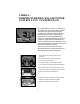
OPERATING INSTRUCTIONS ALARM/MODE DISPLAY DISPLAY ALARM SYMBOLS DOT INDICATORS POWER BEING DELIVERED TO LOAD OVER TEMPERATURE THERMOCOUPLE OPEN MANUAL MODE ON (DISPLAY INDICATES PERCENTAGE OF POWER) NO HEAT REMOTE AND STANDBY OPERATION UNDER TEMPERATURE THERMOCOUPLE REVERSED DIGITAL SETPOINT SWITCH ACCURATELY SETS A SETPOINT TEMPERATURE TEMPERATURE AND PERCENTAGE POWER DISPLAY STANDBY (WARM) REGION PERCENTAGE POWER ADJUSTMENT KNOB CONTROLS PERCENTAGE OF POWER SUPPLIED TO LOAD IN MANUAL POWER SW
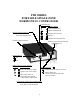
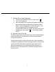
PIM SERIES PORTABLE SINGLE ZONE HORIZONTAL CONTROLLER ALARM/DISPLAY DISPLAY ALARM SYMBOLS OVER TEMPERATURE UNDER TEMPERATURE DIGITAL SETPOINT SWITCH ACCURATELY SETS A SETPOINT TEMPERATURE THERMOCOUPLE OPEN NO HEAT THERMOCOUPLE REVERSED STANDBY (WARM) REGION TEMPERATURE AND PERCENTAGE POWER DISPLAY POWER SWITCH ON OFF MODE SELECT TOGGLE SWITCH DISPLAY MODE SYMBOLS DOT INDICATORS OPEN LOOP (MANUAL MODE) POWER BEING DELIVERED TO LOAD CLOSED LOOP (AUTO MODE) MANUAL MODE ON (DISPLAY INDICATES PERCENTA
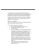
OPERATING INSTRUCTIONS IMP Series 15 and 30 Amp Temperature Controllers PIM Series 10 and 15 Amp Temperature Controllers Section I. General Description The IMP and PIM Series are microprocessor based PID controllers specifically designed to perform most operator functions automatically. The IMP Series are plug-in units, while the PIM Series are portable, stand-alone instruments.
The IMP plug-in controller is capable of receiving a standby command from the SAM auxiliary module. When a standby or low heat command is acknowledged from the SAM during closedloop operation, the controller will operate with a fixed setpoint. When receiving a standby command during open-loop operation, the output power of the controller will be reduced to 1/4 of the front panel power control setting.
To install a plug-in controller into a mainframe, release the locking device on the lower edge of the unit by pulling the plunger gently away from the panel. Align the upper and lower edges of the printed circuit board on the controller with the mainframe card guide slot and slide in until the rear connector is completely engaged. Lock the controller into the frame by depressing the plunger on the locking device. Section III.
6- B. When any of the thermocouple (TC) faults are detected, output power will be cut-off automatically and the temperature display will be blanked out. The leftmost digit will show “ ” for (TC open), “ ” for (TC reverse) or “ ”for No Heat and flash twice per second. Automatic Operation with CompuStep ® system When starting from cold, it is recommended that the CompuStep system be used, as this will serve to lengthen heater life considerably. 1- Position the mode select switch to CompuStep mode (“ ”).
C. Manual Open-Loop Operation 1- Position the mode select switch to open-loop (“ ”). 2- Turn the AC power on. 3- After reset delay, the controller will display the percentage of output power as adjusted by the power control knob. The percentage power indicator will be on. Thus 0.00 corresponds to 0% (no power) and 1.00 corresponds to 100% (full power). The leftmost digit will display open-loop mode ( “ ” ). 75% power is shown as 0.75. D.
Procedure for Manual Control Pre-Set 1- Adjust controller for closed-loop operation and obtain good molded parts. This will adjust the controller to the proper temperature. 2- Position the module select switch to open-loop and set the manual control knob to roughly 25%. Wait for 10 seconds, than momentarily switch to closed-loop mode to examine the temperature. If it is above the setpoint, the manual power is too high to maintain proper temperature. If it is below setpoint, the manual power is too low.
on, indicating that the remote standby function is active. b- If the controller is in open-loop mode, the power output is reduced to 1/4 of the value adjusted by the power control knob. Notice that the % power display will show the reduced value. The remote standby indicator will be on. F. 1- 2- Faults Overtemperature alarm: A constant overtemperature alarm is most likely caused by a shorted triac in the controller or incorrect or shorted mold wiring.
3- 4- Thermocouple open or reversed: If any TC fault is detected during closed-loop operation, the output power will be cut off. If it is necessary to apply power to the load during a TC fault condition, the controller can be switched to manualmode. The output power will be a function of the manual control knob setting. Since the controller is now operating in open-loop mode, extreme care must be taken when adjusting to prevent excess output power which would overheat the load.
What to do: A. Try resetting the controller by turning its AC power OFF and then ON. B. If “No Heat” persists, then the problem could be one of the following. a- Open heater or load. b- Thermocouple shorted. Switch to manual mode to override this condition. c- Load circuit open. This can be caused by an open power cable, an open connector or a failed triac in the controller. Exchange the module with a known good module to eliminate suspect triac or module. d- Slow heater.
34- For 120 Vac input operation, install the 2 jumpers on the PC board as shown. For 240 Vac input operation, install the 1 jumper on the PC board as shown.
OPERATING INSTRUCTIONS Model SAM Communications Module Section I. Installation CAUTION Never insert or remove the module from a main frame with the AC power on. Always switch the module or main frame to “off.” Hazardous potentials exist on components inside both the module and main frame. Always disconnect the AC power to the main frame when servicing. SAM must be used in conjunction with a model ”MFC“ communications-type main frame, and one or more IMP type microprocessor-based temperature controllers.
Section II.
QUICK REFERENCE GUIDE SPEAKER FAST HIGHER TONE = OVER TEMPERATURE 30°F (17°C) OR MORE ABOVE SETPOINT SLOW LOWER TONE = UNDER TEMPERATURE 30°F (17°C) OR MORE BELOW SETPOINT LOW TEMP ALARM MODE SWITCH LOW TEMP ALARM MODE INHIBIT LOW TEMP ALARM ACTIVE EXTERNAL OUTPUT CONNECTOR PINS 1&2 - N.C. RELAY CONTACTS OVER TEMP. LED (red) UNDER TEMP. LED (red) PINS 1&3 - N.O.
Section III. Basic Operation 3.1 3.2 3.2.1. 3.2.2. 3.3. 3.4. Select Normal or Standby Mode. Select Low Temperature Alarm Mode. Low Temperature Alarm Inhibit : Speaker will be off and output relay inactive in the event of low temperature condition (useful during start-up procedures). Low Temperature Alarm Active : 30°F (17°C) or more below IMP setpoint temperature will sound alarm and energize output relay contacts. Turn Power On-Off Switch to ”ON“ position. Alarm indications are automatic.
4.2 Alarm Indications: When an overtemperature or undertemperature condition exists in any zone occupied by an IMP controller, both audio (tones) and visual (LED) alarms will occur in the SAM. a. Over Temp. : Occurs when an IMP thermocouple is 30 deg F (17 deg C) or more above setpoint. The speaker will emit a higher pitched audio tone of about 2 KHz repeating about twice per second. At the same time, the over temper ature LED will flash, and relay closure will occur. b. Under Temp.
4.4 Low Temperature Alarm Mode Switch: This switch gives the operator the ability to defeat both the low temperature audio alarm, and output connector relay operation. This feature is useful to avoid sounding an alarm during startup or cooling down procedures. The undertemperature LED is unaffected by this switch. All overtemperature alarm indications are also unaffected by this switch. a. Low Temp. Alarm Active : In this position, undertemperature alarm indications operate normally. b. Low Temp.
NOTES 21
MOLD (FEMALE) (MALE) v CABLE END CKPTM1 v CABLE END CKPTF1 CABLE MPTC10 (10 FOOT) MPTC20 (20 FOOT) MAINFRAME CONNECTOR CKPTOC1 MOLD CONNECTOR CKPTIC1 POWER OUT AND THERMOCOUPLE PIM1B15 NEMA IN, 5 PIN OUT CKPTM1 PIM1A15 NEMA IN, NEMA OUT POWER IN AC2024F OUTPUT AC INPUT OUTPUT FEMALE PLUG 22 THERMOCOUPLE INPUT POWER OUT THERMO COUPLE AC1524M M2MJ AC INPUT MALE PLUG MALE PLUG
PIM1A10 POWER CORD IN, 5 PIN OUT AC INPUT OUTPUT 23