SERIES OTC25 N/L/P DIGITAL TEMPERATURE CONTROLLERS Instruction Manual
Introduction Congratulations on your purchase of an Athena Series OTC25 Digital Temperature Controller. It is designed for ease of use and reliability wherever accurate temperature control is required. After following the instructions for installation, simply step through and set each of the unit’s parameters using the OTC25’s easy menu system. If you still have questions or require any assistance in setting up or operating your controller, please contact your Athena representative or call 1-800-782-6776.
Table of Contents Installation Mounting Wiring Operation 1 1 2 OTC25 N On/Off Controller OTC25 L Limit Controller OTC25 P PID Controller 2 4 5 7 Calibration Error Codes IEC Requirements Warranty/Repair Information Technical Specifications 10 11 11 12 14
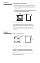
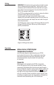
Installation Pre-Installation Instructions 1. Inspect shipping carton for obvious signs of mishandling. 2. After removing the controller from the shipping carton, inspect it carefully for damage. Never attempt to install and use a damaged unit. 3. Verify that the ordering code number indicated on the side of the controller matches what was ordered. 3.780” 3.780" (96mm) (96 mm) 0.25” 0.25" (6.35mm) (6.35 mm) 3.5” 3.5" (88.9mm) (88.9 mm) °F 3.780" 3.
Wiring IMPORTANT: All electrical wiring connections should be made only by trained personnel using Class 1 wiring, and in strict accordance with the National Electrical Code and local regulations. Both of the incoming power lines should be fused with 2AG, 0.5 A maximum rated fuses. The OTC25 controller has built-in circuitry to reduce the effects of electrical noise (RFI) from various sources; however, power and signal wires should always be kept separate.
OTC25 N Operation To enter the configuration menu, press and hold the Parameter key for 10 seconds until the display changes to the parameter mode. Press the Parameter key again to index through the available parameters. Pressing the Parameter Key for 3 seconds or allowing 60 seconds of inactivity will cause the OTC25 N to exit the menu system and return to normal operating mode.
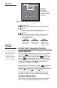
Operation ° ACTUAL SETPOINT HEAT Three-Digit LED Display Displays measured temperature, setpoint, or parameter labels and settings. Figure 4. Front Panel Controls and Indicators Parameter Key Used to access available parameters to set or change values. Raise Key Used to scroll up through available parameter settings or to increase values. (Hold for fast-step progression) Lower Key Used to scroll down through available parameter settings or to decrease values.
OTC25 N Operation Deviation Band Alarm A Deviation Band is a pre-set number of degrees, plus and minus, around the Setpoint Value, ex. +10° F. A Deviation Band Alarm provides an indication to the operator that the Actual Temperature has either exceeded or dropped below the chosen deviation. This parameter can be turned off or adjusted from 1 to 252° F (1 to 140° C).
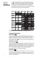
OTC25 L Operation Parameter Range °F Range °C 0 to 905 0 to 485 Low Calibration Fixed Fixed High Calibration Fixed Fixed Display Options Default Default °F °C Default Display Limit Setpoint Operator Selectable Automatic Startup Reset Display Units Figure 5b. Series OTC25 L Parameters and Default Settings Parameter Descriptions Default Display This parameter determines whether the OTC25 L’s display shows the Limit Setpoint or the actual temperature by default.
OTC25 P Operation OTC25 P PID Temperature Controller Normal Operation The factory default display setting of the OTC25 P is for Actual Temperature . The default display may be changed to setpoint temperature by selecting Setpoint at the Default Display parameter selection. When the Default Display is changed to Setpoint, the setpoint temperature may be adjusted by using the Raise or Lower keys. The setpoint is adjustable from 0 to 999° F (-17 to 537° C).
OTC25 P Operation Parameter Range °F Range °C Display Options -126 to 126 -70 to 70 1 to 995 1 to 552 Operator Selectable Operator Selectable Default Default °F °C Default Display Display Offset Proportional Band Rate 0 to 250 sec. Reset 0 to 999 sec. Heat Cycle Time 0 to 120 sec. Cool Cycle Time 0 to 120 sec. Deviation Band Alarm 1 to 252 1 to 140 Fixed Fixed Fixed Fixed Output 2 Configuration Display Units Input Type Low Calibration High Calibration “J” TC “K” TC Figure 5c.
OTC25 P Operation Proportional Band Proportional Band is a PID parameter that represents the amount of deviation of the controlled variable required to move through the full range, expressed in % of span or degrees of temperature. This parameter can also be expressed as “Gain” (the wider the band, the lower the gain). Rate Rate is a PID parameter (Derivative Action) that produces a corrective signal proportional to the rate at which the controlled variable is changing.
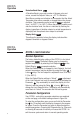
Calibration The Calibration High and Calibration Low selections are accessible only when the calibration jumper is installed (Figure 6). Calibration , Calibration of the OTC25 controller requires the operator to apply two separate fixed and specific signals (Calibration Low and Calibration High) from a reference source (thermocouple calibrator) to the controller. The Raise Key “tells” the controller to read the applied signal and use it as a reference point. Figure 6. Location of Calibration Jumper.
Calibration parameter. The display will alternately flash this mnemonic and the temperature value it expects to see. 8. Adjust the reference source to output a voltage equivalent to that generated by a “J” or “K” (OTC25 P) thermocouple at the temperature flashing on the display. (Allow reference to settle for 10 seconds before proceeding.) 9. Repeat Step 6 for this reference point. 10. Press the Parameter Key for 10 seconds or allow 60 seconds of inactivity. 11.
Warranty/Repair Information Two-Year Limited Warranty THIS EQUIPMENT IS WARRANTED TO BE FREE FROM DEFECTS OF MATERIAL AND WORKMANSHIP. IT IS SOLD SUBJECT TO OUR MUTUAL AGREEMENT THAT THE LIABILITY OF ATHENA CONTROLS, INCORPORATED IS TO REPLACE OR REPAIR THIS EQUIPMENT AT ITS FACTORY, PROVIDED THAT IT IS RETURNED WITH TRANSPORTATION PREPAID WITHIN TWO (2) YEARS OF ITS PURCHASE.
Warranty/Repair Information Unit Repairs It is recommended that units requiring service be returned to an authorized service center. Before a controller is returned for service, please consult the service center nearest you. In many cases, the problem can be cleared up over the telephone. When the unit needs to be returned, the service center will ask for a detailed explanation of problems encountered and a Purchase Order to cover any charge. This information should also be put in the box with the unit.
Technical Specifications Operating Limits Ambient Temperature Relative Humidity Tolerance Power Sensor Range Type J Thermocouple Type K Thermocouple Performance Accuracy Setpoint Resolution Repeatability Temperature Stability TC Cold-End Tracking Noise Rejection Temperature Sampling Control Characteristics Control Hysteresis Display Offset Mechanical Characteristics Display Display Height Color Front-Panel Cutout Bezel Outside Dimensions Bezel Height Case Depth Weight Connections Contacts 32° F to 140° F
Technical Specifications Input Source (Temperature Sensor) Type J OTC25 N/L: OTC25 P: Type K OTC25 N/L: OTC25 P: Thermocouple Range: 6 to 926° F (-14 to 496° C) 32 to 999° F (0 to 537° C) N/A 0 to 999° F (-17 to 537° C) Output Source (Power to Heater) Solid-State Relay (Output 1) 120/250 Vac, Zero-Voltage Switched, 2 A Continuous/ 10 A Surge @ 25° C Solid-State Relay (Output 2) 120/250 Vac, Zero-Voltage Switched, 0.
NOTES 16
Keep This Information in a Safe Place Configured Parameters Reference Information Series OTC25 Temperature Controller Model Number: _____________________ Zone Location: _____________________ Firmware Version No. : _______________ (Displayed when the controller is powered up after all the segments on both lines of the display have been tested).
NOTES 18
Keep This Information in a Safe Place Configured Parameters Reference Information Series OTC25 Temperature Controller Model Number: _____________________ Zone Location: _____________________ Firmware Version No. : _______________ (Displayed when the controller is powered up after all the segments on both lines of the display have been tested).
NOTES 20
For technical assistance, call toll free 1-800-782-6776 (in the U.S.) or 610-8282490 (from anywhere in the world), or e-mail techsupport@athenacontrols.com. Athena Controls, Inc. 5145 Campus Drive Plymouth Meeting, PA 19462 USA Toll-free: 800.782.6776 Tel: 610.828.2490 Fax: 610.828.7084 techsupport@athenacontrols.com athenacontrols.