2/4/8-Port VGA Splitter with Audio VS0102 / VS0104 / VS0108 User Manual www.aten.
VS0102 / VS0104 / VS0108 User Manual FCC Information This equipment has been tested and found to comply with the limits for a Class A digital device, pursuant to Part 15 of the FCC Rules. These limits are designed to provide reasonable protection against harmful interference in a residential installation. This equipment generates, uses and can radiate radio frequency energy, and if not installed and used in accordance with the instruction manual, may cause interference to radio communications.
VS0102 / VS0104 / VS0108 User Manual User Information Online Registration Be sure to register your product at our online support center: International http://support.aten.com North America http://www.aten-usa.
VS0102 / VS0104 / VS0108 User Manual Package Contents The VS0102 / VS0104 / VS0108 package consists of: 1 VS0102 / VS0104 / VS0108 2/4/8-Port VGA Splitter with Audio 1 Power Adapter 1 User Instructions* Check to make sure that all the components are present and that nothing got damaged in shipping. If you encounter a problem, contact your dealer.
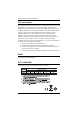
VS0102 / VS0104 / VS0108 User Manual Contents FCC Information . . . . . . . . . . . . . . . . . . . . . . . . . . . . . . . . . . . . . . . . . . . . . ii RoHS. . . . . . . . . . . . . . . . . . . . . . . . . . . . . . . . . . . . . . . . . . . . . . . . . . . . . . ii SJ/T 11364-2006. . . . . . . . . . . . . . . . . . . . . . . . . . . . . . . . . . . . . . . . . . . . . ii User Information . . . . . . . . . . . . . . . . . . . . . . . . . . . . . . . . . . . . . . . . . . . . .iii Online Registration . .
VS0102 / VS0104 / VS0108 User Manual Verification . . . . . . . . . . . . . . . . . . . . . . . . . . . . . . . . . . . . . . . . . . . . . 19 Powering Off and Restarting. . . . . . . . . . . . . . . . . . . . . . . . . . . . . . . . . . . 19 Appendix Safety Instructions . . . . . . . . . . . . . . . . . . . . . . . . . . . . . . . . . . . . . . . . . . 20 General . . . . . . . . . . . . . . . . . . . . . . . . . . . . . . . . . . . . . . . . . . . . . . . . 20 Technical Support. . . . . . . . . . . . . .
VS0102 / VS0104 / VS0108 User Manual About this Manual This User Manual is provided to help you get the most from your system. It covers all aspects of installation, configuration and operation. An overview of the information found in the manual is provided below. Chapter 1, Introduction, introduces you to the VS0102 / VS0104 / VS0108 system. Its purpose, features and benefits are presented, and its front and back panel components are described.
VS0102 / VS0104 / VS0108 User Manual Conventions This manual uses the following conventions: Monospaced Indicates text that you should key in. [] Indicates keys you should press. For example, [Enter] means to press the Enter key. If keys need to be chorded, they appear together in the same bracket with a plus sign between them: [Ctrl+Alt]. 1. Numbered lists represent procedures with sequential steps. ♦ Bullet lists provide information, but do not involve sequential steps.
Chapter 1 Introduction Overview The ATEN VS0102 / VS0104 / VS0108 2/4/8-Port VGA Splitter with Audio are VGA splitters that allow a single VGA video & audio signal to be distributed to two, four, or eight output displays with independent stereo control. The VS0102 and VS0104 support up to 450 MHz video bandwidth, and the VS0108 supports up to 400 MHz video bandwidth , which provides optimum video quality, supported by resolutions up to 1920x1440.
VS0102 / VS0104 / VS0108 User Manual Features One video input to 2/4/8 video outputs Superior video quality – up to 1920 x 1440 @ 60Hz Supports up to 450 MHz bandwidth (VS0102/VS0104), and 400 MHz bandwidth (VS0108) for high performance video Long distance transmission – up to 65m Supports VGA, SVGA, UXGA, WUXGA, and multisync EDID Expert -- selects the optimum EDID settings for smooth power-up and highest quality display Expandable – provides up to 8/64/512 video displays RS-232 chain cont
Chapter 1.
VS0102 / VS0104 / VS0108 User Manual Components VS0102 / VS0104 / VS0108 Front View 1 2 No Component Function 1 Power Pushbutton Push this button to turn on / off the switch. 2 Power LED The LED (green) lights up when the switch is powered on. The LED (orange) lights up to indicate that the switch is in standby mode.
Chapter 1. Introduction VS0104 Rear View 2 3 1 4 5 VS0108 Rear View 2 3 1 4 No 5 Component Function 1 Grounding Terminal The grounding wire used to ground the unit attaches here. 2 RS-232 Serial Port This is the serial remote port for input source selection and high-end system control. 3 Video / Audio Output Each video output section is comprised of a VGA connector and a mini stereo audio jack. The cables that connect to the video and audio ports on the display devices plug in here.
Chapter 2 Hardware Setup 1. Important safety information regarding the placement of this device is provided on page 20. Please review it before proceeding. 2. Make sure that the power to all devices connected to the installation are turned off. 3. Make sure that all devices you will be installing are properly grounded. Rack Mounting For convenience and flexibility, the VS0102 / VS0104 / VS0108 can be mounted on system racks. To rack mount a unit do the following: 1.
Chapter 2. Hardware Setup 2. Screw the bracket into any convenient location on the rack. Note: These screws are not provided. We recommend that you use M5 x 12 Phillips Type I cross, recessed type screws. Grounding To prevent damage to your installation it is important that all devices are properly grounded. 1. Use a grounding wire to ground the VS0102 / VS0104 / VS0108 by connecting one end of the wire to the grounding terminal, and the other end of the wire to a suitable grounded object. 2.
VS0102 / VS0104 / VS0108 User Manual Installation Single Stage Installation of the VS0102 / VS0104 / VS0108 is simply a matter of plugging in the appropriate cables. To install the splitter, refer to the installation diagram on page 10 as you perform the following steps: 1. Use a VGA/Audio cables to connect the VGA/Audio output ports on the source device to the VGA/Audio input ports on the VS0102 / VS0104 / VS0108. 2.
Chapter 2. Hardware Setup OR 2 5 3 4 1 Installing the RS-232 Controller In order to use the RS-232 serial interface to attach a high-end controller (such as a PC) to the splitter, use a RS-232 serial cable. The end connecting to the VS0102 / VS0104 / VS0108 should have a 9-pin male connector. Refer to step 5 on the diagram above. Note: To configure the controller serial port, see page 11.
VS0102 / VS0104 / VS0108 User Manual Cascade To provide video/audio displays for more monitors, additional video splitters can be cascaded. Use a high density HDB-15 male/female video/audio extender cables to connect any available video/audio output port on the higher level video splitter to the video/audio input port of the lower level Video Splitter.
Chapter 3 Operation Overview The VS0102 / VS0104 / VS0108 2/4/8-Port VGA Splitter with Audio offers simple plug and play operation. To use the splitter, simply connect your hardware as instructed in Chapter 2, power on all devices in your setup, and the splitter expands your source signal across two (VS0102), four (VS0104), or eight (VS0108) video displays. The remainder of this chapter describes the RS-232 serial interface, and how to power off/restart your device.
VS0102 / VS0104 / VS0108 User Manual Switch Port Commands The formula for Switch Port commands are as follows: 1.
Chapter 3. Operation Command for Cascaded Splitters Serial port commands for cascaded splitters require identifying the chain of ports to which the target device is connected.
VS0102 / VS0104 / VS0108 User Manual EDID Mode Selection Commands Extended Display Identification Data (EDID) is a data format that contains a display's basic information and is used to communicate with the video source system. You can set up which EDID mode the VS0102 / VS0104 / VS0108 uses with the commands that follow.
Chapter 3. Operation Mute Commands To enable or disable audio coming from the output port, use the following commands.
VS0102 / VS0104 / VS0108 User Manual Firmware Update Command The Firmware Update feature readies the VS0102 / VS0104 / VS0108 for a firmware upgrade.
Chapter 3. Operation Read Command The Read command allows you to read information about the VS0102 / VS0104 / VS0108.
VS0102 / VS0104 / VS0108 User Manual The following table shows the available read command list: Command Output Port Control Enter Description read version [Enter] Read device firmware version read edid [Enter] Read EDID information read o yy video [Enter] Read port video on/off status read o yy audio [Enter] Read port audio on/off status read o * video [Enter] Read all port video on/off status read o * audio [Enter] Read all port audio on/off status Reset Device Comman
Chapter 3. Operation Verification After entering a command, a verification message appears at the end of the command line as follows: command ok- indicates that the command is correct and successfully performed by the switch command incorrect - indicates that the command has the wrong format and/or values. Powering Off and Restarting If you power off the VS0102 / VS0104 / VS0108, follows these steps before powering it on again: 1. Power off the attached devices. 2.
Appendix Safety Instructions General Read all of these instructions. Save them for future reference. Follow all warnings and instructions marked on the device. Do not place the device on any unstable surface (cart, stand, table, etc.). If the device falls, serious damage will result. Do not use the device near water. Do not place the device near, or over, radiators or heat registers. The device cabinet is provided with slots and openings to allow for adequate ventilation.
Appendix If an extension cord is used with this device make sure that the total of the ampere ratings of all products used on this cord does not exceed the extension cord ampere rating. Make sure that the total of all products plugged into the wall outlet does not exceed 15 amperes. To help protect your system from sudden, transient increases and decreases in electrical power, use a surge suppressor, line conditioner, or un-interruptible power supply (UPS).
VS0102 / VS0104 / VS0108 User Manual Rack Mounting Before working on the rack, make sure that the stabilizers are secured to the rack, extended to the floor, and that the full weight of the rack rests on the floor. Install front and side stabilizers on a single rack or front stabilizers for joined multiple racks before working on the rack. Always load the rack from the bottom up, and load the heaviest item in the rack first.
Appendix Technical Support International For online technical support – including troubleshooting, documentation, and software updates: http://support.aten.com For telephone support, Telephone Support, page iii: North America Email Support Online Technical Support support@aten-usa.com Troubleshooting Documentation Software Updates Telephone Support http://www.aten-usa.
VS0102 / VS0104 / VS0108 User Manual Specifications Function Display Connections Connectors Input Output VS0102 VS0104 VS0108 2 4 8 Video 1 x HDB-15 Male (Blue) Audio 1 x Mini Stereo Jack Female (Green) Video 2 x HDB-15 Female (Blue) 4 x HDB-15 Female (Blue) 8 x HDB-15 Female (Blue) Audio 2 x Mini Stereo Jack Female (Green) 4 x Mini Stereo Jack Female (Green) 8 x Mini Stereo Jack Female (Green) RS-232 Port 1 x DB-9 Female (Black) Power 1 x DC Jack Switches Power 1 x Pushbuttons
Appendix Limited Warranty IN NO EVENT SHALL THE DIRECT VENDOR'S LIABILITY EXCEED THE PRICE PAID FOR THE PRODUCT FROM DIRECT, INDIRECT, SPECIAL, INCIDENTAL, OR CONSEQUENTIAL DAMAGES RESULTING FROM THE USE OF THE PRODUCT, DISK, OR ITS DOCUMENTATION. The direct vendor makes no warranty or representation, expressed, implied, or statutory with respect to the contents or use of this documentation, and especially disclaims its quality, performance, merchantability, or fitness for any particular purpose.