User Manual CS-1004 /CS-1008 /CS-1016 2001-01-13
001-01-13
Packing List The complete Master View package consists of: M One Master View Pro KVM Switch (CS-1004, CS-1008, or CS-1016) M One Power Adapter M One User Manual Check to make sure that the unit was not damaged in shipping. If you encounter a problem, contact your dealer. Read this manual thoroughly and follow the installation and operation procedures carefully to prevent any damage to the unit, and/or any of the devices connected to it. ©Copyright 2000 ATEN International Co., Ltd. Manual Part No.
Contents Overview . . . . . . . . . . . . . . . . . . . . . . . . . . . . . . . . . . . . . . . . . . . . . . . . . . . . . . 1 Features . . . . . . . . . . . . . . . . . . . . . . . . . . . . . . . . . . . . . . . . . . . . . . . . . . . . . . . 2 Hardware Requirements . . . . . . . . . . . . . . . . . . . . . . . . . . . . . . . . . . . . . . . . . . 3 Console . . . . . . . . . . . . . . . . . . . . . . . . . . . . . . . . . . . . . . . . . . . . . . . . . . . . 3 PC . . . . . . . . . . . . . . . . . . .
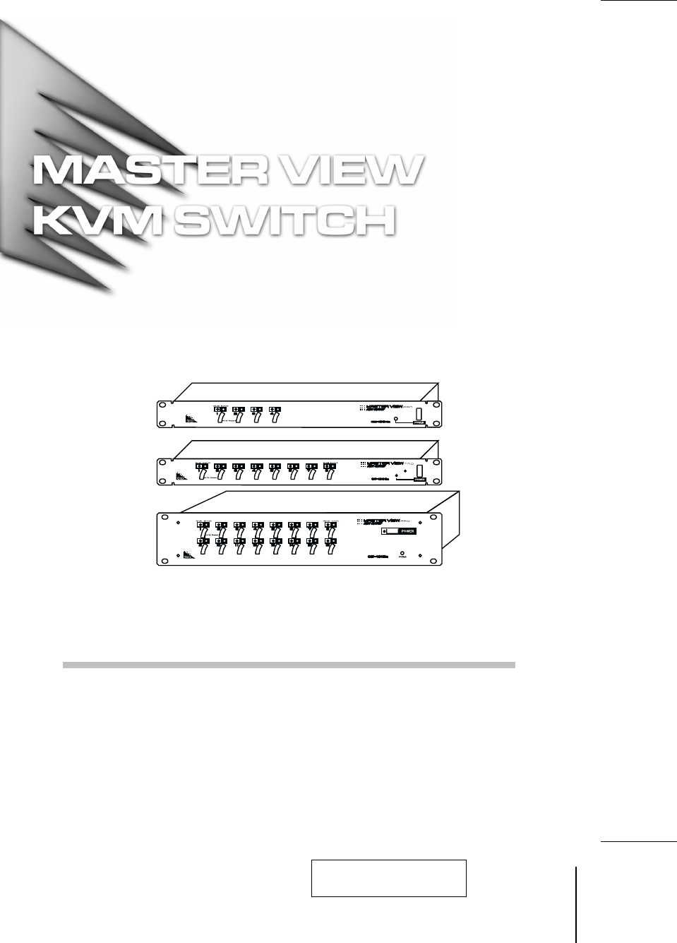
Overview The Master View Pro KVM Switch is a control unit that allows access to multiple computers from a single console (keyboard, monitor, and mouse). Before the development of the Master View, the only way to control multiple computer configurations from a single console was through a complex and costly network system. Now, with the Master View Pro, you can easily access multiple computers in a cost effective manner. Depending on the model, a Master View Pro can control up to 4, 8, or 16 PCs.
Features w Daisy Chain Up To 31 Additional Units - Control Up to 512 PCs From a Single Console w No Software Required - Computer Selection via Front Panel Switches, Hotkeys or OSD (On Screen Display) w Quick View Scan Mode for Monitoring Selected PCs w PS/2 and Serial Mouse Emulation Provided For System Bootup w Console’s PS/2 Mouse Controls All Connected PCs - Even Those With Serial Mice w Support Microsoft Intellimouse Pro, Logitech FirstMouse, MouseMan.
Hardware Requirements Console w A VGA, SVGA, or Multisync monitor capable of the highest resolution that you will be using on any computer in the installation. w A PS/2 style mouse w A PS/2 style keyboard PC The following equipment must be installed on each computer: w A VGA, SVGA or Multisync card. w Either a 6-pin mini-DIN (PS/2 style), or DB-9 (standard serial), mouse port.
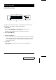
Unpacking CS-1016 Front View: * 1 2 4 3 T The figure shows a CS-1016 model. The only difference between it and the other models is in the number of Port Selection Switches. 1. Status LEDs OnLine: Lights ORANGE to indicate that the PC attached to the corresponding port is up and running Selected: Lights GREEN to indicate the currently selected port. 2. Power SwitchK/M Reset 3. Port Selection Switches w Press a switch to access the computer attached to the corresponding port.
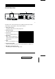
CS-1016 Rear View: * 1 3 4 5 2 6 7 T The figure shows a CS-1016 model. The only difference between it and the other models is in the number of Port Selection Switches. 1. Daisy Chain Section If you daisy chain units, the cables plug in here. 2. CPU Port Section The cables that link to the computers plug in here. 3. Power Jack The power adapter plugs in here. 4. DIP Switch SW 1 - 5: Sets the Station No.
Installation Before you begin, make sure that power to all the devices (Master View Pro and PCs) you will be connecting up have been turned off. First Stage Installation In a Single Stage installation, there are no additional Master View’s daisy chained down from the first unit. To set up a single stage installation do the following: 1.
6. Turn on the power to the Master View. Note: When you turn the unit On, it undergoes a Power On Self Test.
4. Use Daisy chain cable set 2L-1700 (as described in the Hardware Requirements section), to connect from the Chain Out Port of the parent Master View unit to the Chain In Port of the child Master View unit (First Station Out to Second Station In, Second Station Out to Third Station In, etc.). Note: You cannot use the Chain In Port of the First Station Master View, since it is the highest level parent. 5.
Operation Hot Plugging The Master View Pro supports hot plugging - components can be removed and added back into the installation by unplugging their cables from the CPU ports without the need to shut the unit down. In order for hot plugging to work properly, however, these procedures must be followed: w Hot Plugging CPU Ports: When hot plugging cables from the CPU ports: 1. The cable must be plugged back into the same port it was removed from. 2.
Port Selection Controlling all the PCs connected up in your Master View installation from a single console could not be easier. Three methods are available that provide instant access to any PC on the chain: Manual; Hot Key; and OSD. w Manual Simply press the appropriate Port Selection Switch on the Master View’s front panel. After you press the switch, the Selected LED lights to indicate that the port is currently selected. The OSD (see p.
Port ID Numbering Since each CPU Port on a Master View installation is assigned a unique Port ID, you can directly access any computer on any level of the installation using the Hot Key port selection method or from the OSD Main Menu by specifying the Port ID that the computer is connected to. The Port ID is made up of two parts: 1. The Station Number - a two digit number which reflects the Master View’s position in the daisy chain sequence, and 2.
Port Numbering Table Port Numbering is summarized in the following table: 12 Number of Digits Meaning 4 First two for Station Number; second two for Port Number 3 First two for Station Number; third for Port Number 2 Port Number on the Currently Active Station 1 Port Number on the Currently Active Station CS-1004 / CS-1008 / CS-1016 User Manual 2001-01-13
Hot Key Operation Hotkey Port Selection Hot key port selection allows you to conveniently access any computer directly form the keyboard, in stead of having to manually select it with a Port Selection switch. Note: Make sure that DIP Switch 6 (located on the Master View’s rear panel), is set to ON to enable the Hot Key feature under OSD. To select a port with the Hotkey method, do the following: 1. Press the left and right Ctrl Keys [Ctrl+Ctrl] and release both of them at the same time.
Hot Key Broadcasting Commands to all attached PCs (to install software or shut down all the PCs, e.g.), can be broadcast from the console’s keyboard with the following Hot Key combinations: w [Ctrl] + [Alt] + [1] + [Enter] (to initiate the keyboard broadcast) A Broadcast symbol appears in front of the Station ID (if the Port ID is currently displayed on the screen), to indicate that Broadcasting is in effect.
OSD Operation On Screen Display (OSD), provides a menu driven interface to handle the computer switching procedure. Using OSD is a great deal more convenient especially in large, daisy chained installations where it is difficult to keep track of which port a particular computer is attached to. All operations start from the OSD Main Menu. To pop up the Main Menu, tap either Ctrl key twice.
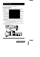
OSD Main Menu Headings Heading Explanation SN-PN This column lists the Port ID numbers (Station Number - Port Number) for all the CPU ports on the installation. The simplest method to access a particular computer is move the Highlight Bar to it, then press [Enter]. QV If a port has been selected for Quick View scanning (see F2 and F4, below), an arrowhead displays in this column to indicate so. PC Lists all the computers that are Powered On and are On Line.
w F2 Scan: Pressing [F2] initiates Quick View Scanning, in which the OSD cycles through all the ports that are currently selected in the List view (see F3, below), and displays each one for the amount of time set with the Scan Duration setting under the F6 Set function (see p. 19). When you want to stop at a particular location, press the [Spacebar] to stop scanning. Note: 1.
To make a choice move the Highlight Bar to the choice you want, then press [Enter]. An icon appears before the choice to indicate that it is the currently selected one. Note: 1. You can access any port on any list by using the Navigation Keys then pressing [Enter]. or double clicking on it with the mouse. 2. If you select a port that does not have a computer attached to it, or if the attached computer is powered Off, the OSD will still switch to it, and will not show an error.
w F6 Set: When you press [F6] a submenu appears that allows you to configure the OSD settings. To change a setting, use the Up and Down Arrow Keys or mouse to move the highlight bar to it, then press [Enter] or Double Click the left mouse button. Selecting Port ID Display Duration, Port ID Display Position, Port ID Display Mode, and Scan Duration brings up submenus of their own with choices for you to select.
Factory Default Settings The factory default settings are as follows: Setting 20 Default Display Duration Always On Display Mode The Port Number plus the Port Number Scan Duration 5 Seconds CS-1004 / CS-1008 / CS-1016 User Manual 2001-01-13
OSD Security Features In order to prevent unauthorized access to the computers, the OSD provides two security features: Password; and Lock/Unlock Console. If a password is set, the console can only be locked/unlocked, by first specifying the password. When the console is locked, only the current monitor screen displays. Attempts to input information from the console have no effect; attempts to switch to a different port, either form console or by pressing the manual switches have no effect, either.
Lock/Unlock Console: To lock/unlock the console: 1. Highlight this item, then press [Enter]. 2. If no password has been set, the system locks the console (if it is unlocked), or unlocks the console (it is locked). To acknowledge the change, the buzzer sounds, and one of the following messages displays on the screen for three seconds: "LOCK CONSOLE OK" (if the console has been locked), or "UNLOCK CONSOLE OK" (if the console has been unlocked). 3.
Appendix Station Numbering Table The first Master View Pro (the one that the console connects to), is considered the First Station; the Master View Pro that daisy chains to it is considered the Second Station; the Master View Pro daisy chained to the Second Station is considered the Third Station, etc.
Troubleshooting Symptom Pressing the HotKeys gets no response under OSD. Pressing Hot Keys gets no response. Possible Cause Action DIP Switch 6 is set to OFF. Make sure that DIP Switch 6 is set to ON. The connection from the selected port to the target computer has been broken, or the PC is turned OFF. Check the Online LED for the selected port. If it is not lit: 1. Manually press one of the Select switches to connect to a computer that is powered ON. 2.
Specifications Function CS-1004 Power Consumption Direct PC Connections CS-1016 DC 9V 500mA DC 9V DC 9V 600mA 800mA 4 8 16 256 512 Max. (via 128 Daisy Chain) Front Panel Switches Hot Keys On Screen Display Port Selection LEDs CS-1008 Power 1 On Line 4 8 16 Selected 4 8 16 Console 1 x 6 pin mini-DIN Female (PS/2 Style Mouse) 1 x 6 pin mini-DIN Female (PS/2 Style Mouse) 2 Earphone Jacks (Mic. and Speaker) 1 HDB-15 Female (std.
Federal Communications Commission Statement This device complies with Part 15 of the FCC Rules. Operation is subject to the following two conditions: (1) this device may not cause harmful interference, and (2) this device must accept any interference received, including interference that may cause undesired operation.