PEGASUS-02 P / SKAT-02 P PEGASUS-02 M / SKAT-02 M MITER SAWS OPERATING AND SAFETY INSTRUCTIONS 1 Operating and Safety Instructions
CONTENTS Page 1. General Information 3 1.1. Introduction 3 1.2. Manufacturer 3 2. Machine’s description and purpose of use 3 2.1. Machine’s description 3 2.2. Technical features 5 2.3. Cutting diagram 6 2.4. Overall dimensions 7 2.5. Part lists and technical drawings 8 3. Safety 10 3.1. Safety information 10 3.2. Accident prevention 10 3.3. General safety information 11 4. Transport of the machine 12 5. Installation of your machine 13 5.1. Preparation 13 5.2.
1. GENERAL INFORMATION 1.1. INTRODUCTION The user’s manual given by the manufacturer contains necessary information about the machine parts. Each machine operator should read these instructions carefully, and the machine should be operated after fully understanding them. Safe and efficient use of the machine for long term depends on understanding and following the instructions contained in this manual. The technical drawings and details contained in this manual constitute a guide for the operator. 1.2.
Please mention the below mentioned data in all your correspondence regarding the machine with the manufacturer and/or your ATECH dealer.
2.2. TECHNICAL FEATURES Technical Features (American) SKAT-02 P 3 HP 220V/440V 60Hz d=1 " D=16" 3000 rpm -- -- 26x24x30" 154 lbs SKAT-02 M 3 HP 220V/440V 60Hz d=1 " D=16" 3000 rpm 90-120 psi 0.
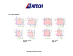
2.3.
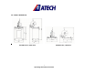
2.4.
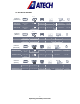
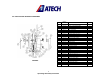
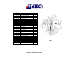
2.5. PARTS LIST AND TECHNICAL DRAWINGS No. 20 21 22 24 26 28 30 31 37 38 39 40 42 44 45 47 48 49 50 51 52 54 56 59 60 61 64 65 66 67 68 PEGASUS 8 Operating and Safety Instructions ORDER No.
No. 20 21 22 24 26 28 30 31 37 38 39 40 42 44 45 47 48 49 50 51 52 54 56 59 60 61 64 65 66 67 68 Order No.
3. SAFETY 3.1. SAFETY INFORMATION The symbols shown hereunder are necessary to be read with special attention. Not reading or observing of them may cause damage to the equipment or personal injury. IMPORTANT The IMPORTANT symbol above is one telling to apply special care and to be careful at carrying out the specified operation. CAUTION ! The CAUTION! Symbol above warns you against specific dangers, and requires to read the text. Not observing may cause damage to the equipment.
3.2.4. Machine should be operated only by staff members, who have read and understood the contents of this manual. 3.2.5. All directives, recommendations and general safety rules contained in this manual have to be observed fully. The machine cannot be operated in any way for purposes other than those described herein. Otherwise, the manufacturer shall not be deemed responsible for any damages or injuries. And such circumstances would lead to the termination of the warranty. 3.3.
3.3.9. Don’t use any materials other than those recommended by the manufacturer for cutting operations on the machine. 3.3.10. Ensure that the work piece is clamped appropriately by the machine's clamp or vice. 3.3.11. Ensure safe working position, always keep your balance. 3.3.12. Keep your machine always clean for safe operation. Follow the instructions at maintenance and replacement of accessories. Check the plug and cable regularly. If damaged, let it replace by a qualified electrician.
5. INSTALLATION OF THE MACHINE The machine should be located at least 40 cm in front of the back wall. The machine is equipped with a burr collection bag connector and power supply socket on the back side. 5.1. PREPARATION 5.1.1. The outer dimensions of the machine are stipulated in the Dimensions page (Page 6). The ground, where the machine will be placed, should be even, solid enough to bear the weight of the machine. 5.1.2.
5.2. ELECTRIC CONNECTION 5.2.1. The three-phase power cable socket has to be in accordance with the socket on the machine. 5.2.2. Use a connection cable socket in accordance with the CE Safety Directives. 5.2.3. Check the inlet power supply before powering the machine. See Page 19 Item 3.8.3. CAUTION ! * The socket connections have to be made by a qualified electrician, the rotation direction of the saw blade has to be observed by starting the machine.
The electric socket connections have to be checked and corrected by a qualified electrician. The rotation direction of the saw blade should not be defined before testing. 6. MACHINE SAFETY INFORMATION 6.8.1. It is not allowed to operate the machine with the protective cover and other protective equipment removed. 6.8.2. Your machine operates with 220V/440V ~ 3-Phase 60Hz (400V ~ 3-Phase 50Hz) . Let the electric installation of your machine carry out by a qualified electrician only. 6.8.3.
7. OPERATION The miter saws PEGASUS / SKAT cut non-ferrous aluminum, PVC profiles and PVC materials. The operator adjusts (manually via knob) the cutting speed of the saw blade according to the material type to be cut. Inner and outer sharp edges of the carbide tipped circular saw blade ensures high quality clean cutting results. The cutting length can be precisely read and adjusted using the measuring tape fixed to the back fence.
Pressure Adjustment Button Oil Depot Manometer Oil Filling Tap Air Pressure and Water Discharge Screw Illustration 3 7.1.1. Place the material to be cut on the machine table, take the measure the cutting length using the measuring tape on the back fence, and clamp the work piece (pneumatically or manually). 7.1.2. Start to operate the saw blade by pressing the Start button. 7.1.4. Carry out the cutting operation by pressing down the cutting head holding the grip. 7.1.5.
7.2. MITER CUT: 7.2.1. Press the saw blade down until it touches the cutting slot of the table. 7.2.2. Pull out the snap pin from its slot. (See Illustration 4) 7.2.3. Pull the table locking Bar to the left to unlock. (See Illustration 4) 7.2.3. Adjust the desired angle by turning the cutting head to the right or left. (See Illustration 5) 7.2.4. The cutting angles 15°-22.5°-30°-45° are fixed by releasing the snap.
Figure-4 CAUTION ! Always ensure that the clamps are positioned outside of the operation area of the saw blade. CORRECT WRONG 8. SAFE INSTALLATION OF THE SAW BLADE 8.1 To remove the circular saw blade from the blade shaft, follow the instructions below. 8.1.1. Remove the M8 screw (Figure 4, No. 55) by turning it counter clockwise with a 8 mm hexagonal key. (Hold the saw blade shaft at the opposite end with a 17 mm wrench key and prevent so that the shaft turns. 8.1.2. Remove the washer No.
CAUTION ! 8.1.8. When replacing the saw blade, use the part of the saw blade washer No. 48, which is in accordance with the saw blade shaft diameter. The outer diameter of the blade washer is 30 and 32 mm. . 9. MAINTENANCE 9.1. PERIODIC CHECKS 9.1.1. Ensure that the table and all kind of parts are clean and dry. Degrease and dry the table. Especially ensure that the holding grips are clean and dry. 9.1.2. Remove all burr, chip and foreign materials from all surfaces of the machine.
9.2. MAINTENANCE AT THE END OF THE WORKING DAY 9.2.1. Disconnect electric and pneumatic connections. (Main Switch must be on “0” position) 9.2.2. Remove all burr, chip and foreign materials from the machine surfaces. If it is necessary to clean the inside of the blade guard, remove the front cover, use gloves to protect your hands from the sharp edges of the blade. 9.2.3. If water or water based liquids were used during cutting, dry the machine with a dry cloth after the operation is finished. 9.2.4.
11. ELECTRIC / PNEUMATIC COMPONENTS 11.1 ELECTRIC COMPONENTS ORDER No. PART NAME QUANTITY 163-002 MOTOR QS 90 L 2A H 2.2 kW 400V 3 N PE 50 Hz 1 161-005 LE1-M35Q712 MOTOR PATCHER 1 164-013 4x1,5 mm POWER CABLE H0 7RN-F 3,5 m 165-050 ELECTRIC PLUG 1 11.2 PNEUMATIC COMPONENTS ORDER No.