LIBRA-02 M / LIBRA-02 HM COPY ROUTER User's Manual 1 Operating and Safety Instructions
CONTENTS Page 1. General Information 1.1. Introduction 1.2. Manufacturer 2. Machine’s Description and Purpose of Use 2.1. Machine’s description 2.2. Technical features 2.3. Overall dimensions 2.4. Part lists and technical drawings 3. Safety 3.1. Safety information 3.2. Prevention of accidents 3.3. General safety information 4. Transport of the machine 5. Installation of the machine 5.1. Preparation 5.2. Electric connection 6. Machine’s safety information 7. Operation 7.1. Starting to work 8.
1. GENERAL INFORMATION 1.1. INTRODUCTION The user’s manual given by the manufacturer contains necessary information about the machine parts. Each machine operator should read these instructions carefully, and the machine should be operated after fully understanding them. Safe and efficient use of the machine for long term depends on understanding and following the instructions contained in this manual. The technical drawings and details contained in this manual constitute a guide for the operator. 1.2.
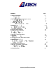
Please mention the below mentioned data in all your correspondence regarding the machine with the manufacturer and/or your ATECH dealer.
2.2.
2.3.
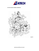
2.4.
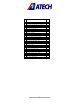
No STOCK NO / PART NAME 3 5 6 7 8 9 11 13 14 15 16 17 18 19 21 22 23 25 26 27 28 29 31 32 33 34 35 141- 093 Washer Diameter 30x8x7 111- 075 Right set square 111-073 Lower motion arm connection 144-006 Motion shaft 111-077 Motion bearing 224-001 Plastic support 141-083 Copy template 111-068 Fixing knob bearing 141-078 Arm pin 145-017 Fixing knob bearing fixing bolt 141-074 Upper limiting pin 111-081 Rear clamping housing 141-267 Support shaft 111-083 Router upper bearing housing 141-085 Router holder shaf
No 36 37 40 47 48 53 58 63 65 66 68 70 71 81 84 88 89 90 91 95 98 99 100 102 103 104 105 STOCK NO / PART NAME 111-080 141-079 192-008 111-078 141-069 141-089 111-070 141-084 204-001 204-002 112-007 111-079 142-021 141-077 111-066 194-002 142-024 144-008 191-004 141-294 141-091 273-001 171-019 141-090 172-030 145-016 550-013 Upper motor lower cover Gas spring connection rod Clamp end 25x35x40 PP Motor cover Bearing shaft connection sleeve Fixing knob shaft bearing Axis bearing Drill bearing support Diamete
DANGER WARNING The DANGER WARNING above warns you against specific dangers, and definitely requires the text to read. Not observing may result in serious bodily injury. Please read the user’s manual carefully before using the machine or carrying out maintenance. 3.2. PREVENTION OF ACCIDENTS 3.2.1 Our machines are manufactured in accordance with EN 60204-1 and EN 292-2 CE safety directives, which cover national and international safety directives. 3.2.
3.3.2. If the power cable should be damaged during operation, don't touch and unplug it. Never use damaged power cables. 3.3.3. Don’t overload machines for drilling and cutting. Your machine will operate more safely with power supply in accordance with the stipulated values. 3.3.4. Don’t place your hands between parts in motion. 3.3.5. Use protective eye glasses and ear plugs. Don't wear oversize clothes and jewels. These can be caught by moving parts. 3.3.6.
3.3.15. If you are required to operate the machine outside, use only appropriate extension cables. 3.3.16. Repairs should be carried out by qualified technicians only. Otherwise, accidents may occur. 3.3.17. Before starting a new operation, check the appropriate function of protective devices and tools, ensure that they work properly. All conditions have to be fulfilled in order to ensure proper operation of your machine.
5.1.4. At the copy router machines LIBRA-02 M/HM, fix the support bars (Figure 4) to the back fence No. 5 using the handle No. 29. Fix the fence support No. 113 with its special screw No. 27.
5.2. ELECTRIC CONNECTION 5.2.1 The three-phase electric cable socket has to be in accordance with the socket on the machine. 5.2.2 At our models LIBRA-02 M the voltage can be chosen as 230V 50 Hz (110V 60Hz) or 400V 50 Hz (220V/440V 60Hz). The voltage at our model LIBRA-02 HM is 400V 50 Hz (220V/440V 60Hz) as per standard. 5.2.3 Plug the machine to a grounded socket. CAUTION ! 5.2.4 Check the supply voltage. The source voltage must be in accordance with the data on the machine’s label. 5.2.5.
7. OPERATION 7.1. STARTING TO WORK 7.1.1 Ensure that the machine table and all kind of parts are clean and dry. Degrease and dry the machine table. Especially ensure that the holding grips and handles are clean and dry. 7.1.2 Clean all surfaces of the machine from chip and foreign particles. Use eye glasses for protection. 7.1.3 Check with the appropriate keys that the router bit and drill bits are tightened well. 7.1.4 Check the router bit and drill bits for wear, bending and breaking.
7.1.15 The router bit and triple drill unit should be moved down only after the regular rotation has been reached. 8. CHANGING THE ROUTER BIT AND DRILL BITS 8.1 If it becomes necessary to replace the router bit for any reason, follow the following order for replacement: 8.1.1 Unplug the machine 8.1.2 With the 2 wrench keys 14 and 17 loosen the router bit holder by turning the bolt of the router bit holder in counter clockwise direction. Remove the router bit from its holder.
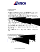
9. ADJUSTING THE AIR PRESSURE OF PNEUMATIC CLAMPS (AT OUR MODELS LIBRA-02 M and LIBRA-02 HM) 9.1. Pull the adjustment button of the conditioner upwards (Fig. 6) a- Turning the adjustment button in clockwise direction increases the pressure b- Turning the adjustment button in counter clockwise direction decreases the pressure 9.2 Once you read 6-8 Bar on the manometer, push the adjustment button of the conditioner down and lock it in that position.
Pressure adjustment button Triple drilling adjustment screw Oil cylinder Manometer Oil filling cap Air pressure and water discharge screw Figure-6 18 Operating and Safety Instructions Figure-7
9.3 In order to prevent that the water inside the air system causes damage to the pneumatic system components, the conditioner unit collects the water in the collection receptacle. Discharge the collected water periodically (at the end of the working day) by pressing the button under the cylinder depot of the conditioner. 9.4 The manufacturer recommends to use the following oils with the conditioner: TELLUS C 10 / BP ENERGOL HLP 10/ MOBIL DTE LIGHT / PETROL OFISI SPINDURA 10. 10. MAINTENANCE 10.
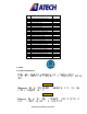
12. ELECTRIC / PNEUMATIC COMPONENTS 11.1 ELECTRIC COMPONENTS STOCK CODE 161-006 162-003 162-004 163-004 163-006 164-002 164-006 164-011 164-014 164-022 164-024 165-009 165-011 165-012 165-016 165-020 165-021 165-025 165-028 165-029 165-031 165-033 165-040 165-048 11.2. PART NAME MAIN SWITCH KG1OB CAPACITOR 25 MF 250 V CONTACTOR LC1 K 0610 M7 SINGLE-PHASE WIRING ROTOR STATOR 0.75 mm CABLE (BLACK) 1.5 mm CABLE (BLACK) 3*1.5 TTR CABLE INTERM. CABLE 2*1 TTR 7*0.
12. TROUBLESHOOTING Here are some recommendations for solving urgent problems. If the trouble cannot be solved, or if you have a problem other than those described hereunder, please contact our technical service or your nearest dealer.