
User Manual
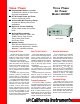

Specifications
California
Instruments
Total Customer Satisfaction
is the goal of all California In-
struments’ employees. It is the
driving force behind everything
we do. This not only affects the
product that you purchase from
California Instruments, but ev-
erything about your interface
with the company. Our applica-
tions engineers are ready to
assist you with your AC power
application. With over 35 years
of experience designing and
building precision AC power
supplies, chances are we can
meet your needs and exceed
your expectations. The same
dedication to customer satis-
faction you will find in our ap-
plications group also perme-
ates our modern manufactur-
ing facility where our products
are carefully built. No unit
leaves our factory without be-
ing thoroughly tested to ensure
quality, reliability and conform-
ance to specifications.
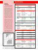
Parameter 2003RP Unit
Controller
Type Programmable
Controls Digital Encoders
Readouts dual 4 digit LCD’s
Output
No. of Phases 3 (A, B, C)
Phase angles A = 0°, B = 240°, C = 120°
AC Power Max. per phase 675 VA
Load Connection floating neutral Rear panel terminal block
Voltage
Ranges High / Low 0-270/0-135 V
RMS
Accuracy
2
16 Hz - 100 Hz ± 0.1 % FS
100 Hz - 2000 Hz ± 0.2 % FS
Resolution 0.1 V
Load Regulation
2
remote sense, 16 - 500 Hz ± 0.1 % FS
Line Regulation 10 % Line change ± 0.02 % FS
T.H.D.
2
(into a 16 Hz - 100 Hz 0.5 typ./ 1.0 max. %
resistive load) 100 Hz - 2000 Hz 1.0 typ./ 2.0 max. %
Output Noise < 0.1 typ. V
RMS
Frequency
Range (see V-F rating chart) 16-5000 Hz
Accuracy ± 0.02 %
Resolution 16.00 Hz - 80.00 Hz 0.01 Hz
80.1 Hz - 800.0 Hz 0.1 Hz
800 Hz - 5000 Hz 1 Hz
Current per Phase (see I-V rating chart)
RMS Current High / Low V range 2.5 / 5.0 A RMS
Peak Current High / Low V range 7.5 / 15.0 A
Protection
Adj. Current limit Resolution 0.1 A RMS
Modes Const. Current or Const. Volt
Over Temperature √
Over Voltage √
Input
Connection Rear panel terminal block
Line Voltage 2 wire + GND 96 - 127 V or 187 - 253 V V RMS
Line Current < 35 A RMS
Line Frequency 47 - 440 Hz
Holdup Time 10 ms
Isolation Input to Chassis/Output 1350 / 2200 V
Measurements
2
- Specifations valid from 300 - 500 Hz, Phase Selectable. (* Requires Option -OP1)
Current Range Low / High 0.000-4.000 / 0.00-6.00 A RMS
Accuracy 0.2 % FS + 0.3 % rdng
Resolution 0.001 / 0.01 A RMS
Peak Current* Range Low / High 0.00-12.00 / 0.0-20.0 A
Accuracy 0.5 % FS + 0.5 % rdng
Resolution 0.01 / 0.1 A
Voltage* Range 0.0 - 300.0 V RMS
Accuracy 0.1 % FS + 0.05 % rdng
Resolution 0.1 V RMS
Power* Range 0.0-800.0 W
Accuracy 0.5 % FS
Resolution 0.2 W
Power Factor* Range 0.00 - 1.00
Resolution 0.01
Remote Control (* Requires Option -OP1)
Interface* RS232C and IEEE-488
IEEE Functions SH1, AH1, T8, L3, RL2
RS232C settings 19200,8,n,1
Command Language SCPI
Remote Inhibit* Output shut down TTL in, active low BNC
Function Strobe* On V or F change TTL out, active low BNC
Physical
Dimensions HxWxD 5.25 x 19 x 22 inches
HxWxD 133 x 483 x 560 mm
Weight (net) 85 / 38.3 lbs / kg
Vibration and Shock Designed to meet NSTA-1A
Temperature Operating 0 to 40 ° C
Storage - 40 to + 85 ° C
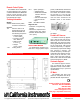
Voltage, Current and Frequency rating charts
Note 1: All specifications are for L-N. Phase angle specifications are valid under balanced load conditions only. Ambient temp. 23° ± 5° C.
Note 2: Supplementary specifications apply outside indicated frequency ranges. 3: At 400 Hz input, nominal line voltage minimum required.