
Manual

Output Relay
Push button controlled or bus
controlled output relay
Output impedance
Programmable Z on 3001iX,
5001iX and 15003iX for 50 Hz
fundamental
Resistive:
range 17 - 1000 mΩ
resolution 4 mΩ
accuracy 2 % FS
Inductive:
range 230 - 1000 µH
resolution 4 µH
accuracy 2 % FS
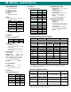
DC Mode Output
Maximum DC power at full scale
of DC voltage range:
Model: Power
3001iX
1500 W
5001iX
2500 W
10001iX
5000 W
15001iX
7500 W
15003iX
2500 W/ø 3ø
7500 W/ø 1ø
Voltage Ranges
User selectable voltage range
combinations:
Range: High Low
270 V 135 V
300 V 150 V
Load Regulation see AC mode
Line Regulation see AC mode
Output Noise < 250 mV
rms
Typ
(20 kHz to 1 MHz) < 500 mV
rms
Max
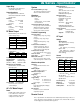
Max. DC Current Capability
Maximum DC current in lowest
DC range pair:
Model 270
range
135
range
3001iX
5.65 11.1
5001iX
9.25 18.5
10001iX
18.5 37.0
15001iX
27.75 55.5
15003iX 1ø
27.75 55.5
3ø 9.25 18.5
Current Limit Programmable
from 0 A to max. current for
selected range.
AC + DC Mode Output
Power
Full AC power if DC component
is less than 20 % of full scale
voltage. Full DC power if DC
component is above 20 %.
System
Non Volatile Memory storage
16 complete instrument setups
200 user defined waveforms
Waveforms
Waveform Types
• Sine
• Square
• Clipped Sine, 0 - 20 % THD
• User defined
User defined waveform storage
Four groups of 50 user defined
arbitrary waveforms of 1024
points for a total of 200. One
group can be active at a time.
Transient Programming
Transient Types
Voltage: drop, step, sag, surge,
sweep
Frequency: step, sag, surge,
sweep
Voltage and Frequency: step,
sweep
Transient List Parameters:
Voltage, Frequency, Time or
cycles, Slew rate, Waveform
shape, Phase angle, Repeat
Transient lists storage
up to 32 transient steps per list
Time resolution 1 msec
Time range 1 msec - 9999 sec
Maximum slew rate
50 µsec for 10% to 90% of full
scale change into resistive load
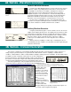
Waveform Acquisition
Channels
Voltage and Current for each
phase.
Memory Depth
4096 samples/channel.
Maximum Sample Rate
39.0625 Ks/s.
Triggering
Auto, Phase, Transient.
Trigger Delay
Pre-trigger 0 - 104 msec 1ø
0 - 312 msec 3ø
Post-trigger 0 - 1000 msec.
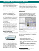
Display
Front panel Graphics Display
with cursors.
Bus Interface
Full bus access to waveform
acquisition system.
Remote Control
IEEE-488 Interface
IEEE-488 (GPIB) talker listener.
Subset:
AH1, C0, DC1, DT1, L3, PP0,
RL2, SH1, SR1, T6
IEEE-488.2 SCPI Syntax
RS232C Interface
9 pin D-shell connector
Handshake: CTS, RTS
Databits: 7,8
Stopbits: 1,2
Baud rate: 9600, 19200,
38400
IEEE-488.2 SCPI Syntax
Supplied with RS232C cable
System Interface
Inputs: Remote shutdown
External Sync
Outputs: Function Strobe
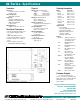
AC Input
Voltage
Model 3001iX:
187 - 264 V
AC
,(L-N, 1 Phase)
All other models:
Standard:
187 - 264 V
AC
,(L-L, 3 Phase)
Option -400:
360 - 528V
AC
,(L-L, 3 Phase)
(Input range must be specified
when ordering)
Current
Input Line Current (per phase)
Model: 187-
264V
360-
528V
3001iX
30 A N/A
5001iX
24 A 12 A
10001iX
48 A 24 A
15001iX
72 A 36 A
15003iX
72 A 36 A
Inrush Current per chassis
< 14 A rms. / 84 A
peak
for 200 µs
@ 187-264 V
< 8 A rms. / 36 A
peak
for 400 µs
@ 360-528 V
Line Frequency: 47 - 63 Hz
Efficiency: 75 % typical
Power Factor: 0.6 typical
Hold-up Time: At least 10 ms
iX Series - Specifications
1
Note 1: Specifications are warranted over an ambient temperature range of 25°± 5° C.
Unless otherwise noted, specifications are per phase for a sinewave with a resistive
load and apply after a 30 minute warm-up period.