Sole Manufacturer and Distributor in the Czech Republic: ATEC v.o.s. Location of factory: ATEC v.o.s.
Type of aeroplane ATEC 212 SOLO Serial number …………………………………………………… Identification label …………………………………………………… LAA CR type licence …………………… issued …………………… This aircraft is not registered at the state office and is to be operated at operator’s own responsibility The aeroplane must be operated according to the information and limits of this flight manual.
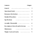
Contents General Chapter ……………………………………. 1 Operational Limits …………………………… 2 Emergency Instructions ……………………… 3 Standard Procedures ……………………… 4 …………………………… 5 Assembly, Disassembly ……………………… 6 Description of Aircraft and its Systems …… 7 …………………………… 8 Specifications Maintenance Weight, Centre of Gravity 3 …………………..
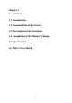
Chapter 1 1. General 1.1. Introduction 1.2. Personal Data of the Owner 1.3. Description of the Aeroplane 1.4. Completing of the Manual, Changes 1.5. Specification 1.6.
1.1. Introduction The information provided by this manual is necessary for an effective and save operation of the ATEC 212 SOLO aircraft. Also included are information and documents of importance from the manufacturer. 1.2.
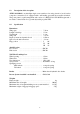
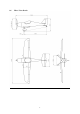
1.3. Description of the Aeroplane ATEC 212 SOLO is an ultralight single-seater cantilever low-wing aircraft of an all carbon composite construction. It is equipped with a tail landing gear with the steerable tail wheel. The power plant is a pull arrangement and consists of a ROTAX 912 UL 80 HP engine and a two-blade or three-blade fix or ground adjustable propeller FITI. 1.4. Specification Dimensions Wing span ……………………………………. Length of fuselage ……………………………. Total height …………………………………….
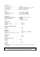
Driving Unit Propeller manufacturer ………………... Type of propeller ……………… Engine manufacturer …………………… Type of engine …………………… Josef Faturik FITI ECO COMPETITION 2 blade, 3-blade Bombardier – ROTAX GmbH ROTAX 912 UL 80 HP Power Take-off power …………………… 59,6 kW / 80 HP / 5800 RPM Maximum continuous power …………… 58 kW / 78 HP / 5500 RPM Cruising power …………………… 37,7 kW / 51 HP / 4800 RPM Engine Speed Maximum take-off engine speed Max. continuous engine speed Cruising engine speed Idling ….… ……. ……. …….
1.6.
Chapter 2 2. Operational Limits 2.1. Introduction 2.2. Air Speeds 2.3. Weights 2.4. Centre of Gravity 2.5. Manoeuvre and Gust Envelope 2.6. Permitted Manoeuvres 2.7. Operational Load Factors 2.8. Type of Operation 2.9. Crew 2.10. Fuel 2.11. Wind 2.12.
2.1. Introduction The chapter 2 contents are operational limits necessary for a save operation of the aircraft 2.2. Air Speeds Never exceed speed vNE ….. 286 km/h ….. 154 kt ….. 101 kt Do not exceed this speed in any case Design manoeuvre speed vA …… 187 km/h Do not use full deflection of the rudders and sudden control operations. Overload of the aircraft may occur Maximum design cruising speed vC …… 238 km/h …..
2.4.
2.5.
2.6. Permitted Manoeuvres Category of the aeroplane: Normal Except of the normal flight manoeuvres, the sharp turns up to bank of 60o, level and climbing turns are permitted. Acrobatics, intended spins and stalls are prohibited 2.7. Operational Load Factors Maximum positive load factor in CG Maximum negative load factor in CG 2.8.
2.11. Wind The safe taking off and landing is possible if the following wind speed limits are not exceeded: a) b) c) taking off or landing against wind taking off or landing tail wind taking off or landing cross wind ………. ………. ………. 2.12. Other limits Smoking and using of mobile telephones is prohibited in the aircraft. Transportation of explosives and free loaded objects is prohibited.
Chapter 3 3. Emergency Instructions 3.1. Engine Failure Taking-Off 3.2. Engine Failure in Flight 3.3. Rescue System Application 3.4. Fire in Flight 3.5. Power-Off Flight 3.6. Emergency Landing 3.7. Safety Landing 3.8. Aborted landing 3.9.
3.1. Engine Failure on Take-Off 1. B. Push stick forward aircraft into gliding attitude and maintain airspeed of 100 km/h (54 kt). Determine the wind direction, adjust flaps for suitable position, turn off fuel valve, switch-off ignition, adjust safety belts and switch-off the master switch just before landing. At a height up to 50 m get the aircraft into landing configuration and carry out a landing with respect for obstructions in take-off direction.
3.6. Emergency landing 1. 2. 3. 4. 5. 6. 7. 8. Carried out in case of engine failure Speed ……………………. 100 km/h ….. 54 kt Adjust safety belts Flaps according to situation Announce the situation by the aeroplane radio station Close the fuel valve Turn off ignition Turn off the main switch In case of emergency landing onto a terrain and surfaces non-approved for light aircraft landings an aircraft damage and crew injury may occur 3.7.
Chapter 4 4. Standard Procedures 4.1 Pre-Flight Inspection 4.1.1 Procedures Before Entering the Cockpit 4.1.2 Procedures After Entering the Cockpit 4.2 Procedures Before Starting the Engine and Starting the Engine 4.3 Warming up the Engine, Engine Check 4.4 Taxiing 4.5 Pre Take-Off 4.6 Take-Off and Climb Away 4.7 Cruising Flight 4.8 Descend and Landing 4.
4.1. Pre-Flight Inspection It is important to carry out a proper pre-flight inspection failure to do so or perform an incomplete inspection could be the cause of an accident. The manufacturer recommends using the following procedure: 4.1.1. Procedures Before Entering the Cockpit 1. 2. 3. Check ignition - turned off. Check main switch – turned off Check the wings, wing surfaces ailerons and flaps, clearances, hinges and connections of the controls, security of the wing pins, Pitot tube.
5. 6. 7. 8. 9. 10. 11. 12. 13. Throttle to idle run Open the choke if the engine is cold Pull up the control stick Main switch on Ignition on Brakes on Start the engine Turn off the choke Warm up the engine until the operating temperature 4.3. Warming up the Engine Start to warm up the engine at 2000 rpm, hold approx. 2 minutes, continue until 2500 rpm till the oil temperature reaches 50oC. Check both ignition circuits according to Art. 4.5. 4.4. Taxiing Recommended speed of taxiing is 15 km/h …..
4.8. Cruising flight ATEC 212 SOLO has good flight features in the whole range of permitted speeds and centre of gravity positions. The cruising speed is in the range 120 – 243 km/h …… 65 – 131 kt. 4.9. Descent and landing Carry out the descent with the throttle in idle run at speed of 100 km/h Flaps position limitations according to Art. 2.2 ….. 54 kt Procedures in the final: 1. 2. 3. 4. Speed 90 km/h …..
Chapter 5 5. Performances 5.1. Introduction 5.2. Stalling Speeds 5.3. Take off Distance at 15 m / 50 ft Height 5.4. Rate of Climb 5.5. Cruising Speeds 5.6.
5.1. Introduction The information in stalling speed and other performances of the ATEC 212 SOLO with ROTAX 912 UL 80 HP and propeller FITI ECO COMPETITION 2b/168. 5.2. Stalling Speeds (CAS) Engine idling Flaps retracted Flaps I (10°) 72 km/h …39 kt 65 km/h ... 35 kt Flaps II (20°) 63 km/h ... 34 kt Flaps III (35°) 62 km/h ... 33 kt Engine stopped 65 km/h ... 35 kt 64 km/h ... 35 kt 5.3. 75 km/h ... 40 kt 67 km/h ...
Chapter 6 6. Assembly and Dismantling 6.1. Introduction 6.2. Dismantling the Horizontal Tail Surface and the Rudder 6.3. Dismantling the Wings 6.4.
6.1. Introduction The assembly of individual parts of the aeroplane is described in this chapter. At least two persons are necessary for the assembly and dismantling. 6.2. Dismantling the Horizontal and Vertical Rudder The HT and VT stabilizers are an integral part of the fuselage Dismantling VT rudder. Disconnect control. Release and unbolt the bolt M6 at the lower part of the rudder. Take out the rudder from the hinges moving it down and backwards. Dismantling elevator.
Chapter 7 7. Description of the Aeroplane and Its Systems 7.1. Wing 7.2. Fuselage 7.3. Tail Surfaces 7.4. The Landing Gear 7.5. Control 7.6. The Driving Unit 7.7. Fuel System 7.8. Instrument Equipment 7.9.
7.1. Wing The cantilever tapered wing with conventional ailerons, slotted flaps and wing-tips. The main spar of laminated beech wood saturated with synthetic resin at a high temperature is placed in the 30% depth of wing. The wing skin is made of carbon sandwich. The wing is reinforced by ribs of plastic and composites, the root ribs are of carbon – nomex honeycomb sandwich. Ailerons and flaps are of all composite construction. The centre-wing section is welded from high quality CrMo steel tubes. 7.2.
7.7. Fuel System The fuel system is formed by an integral fuselage tank with a fuel drain. Double fuel supply circuit with a spare electric pump. The pressure of supplied fuel is measured with a fuelpressure gauge. The fuel reserve 10 l at flight position is indicated by control light. 7.8. Instrument Equipment The instrument equipment consists of basic instruments for flight control, engine control and navigation.
Chapter 8 8. Care and Maintenance 8.1. Maintenance Schedule 8.2. Aeroplane Repairs 8.3. Major Overhaul 8.4. Anchorage of the Aeroplane 8.5.
8.1. Maintenance Schedule Inspection, Mandatory Work Inspection Period 10 25 50 100 200 Engine As per ROTAX Manual attached. Engine Compartment Engine Attachment Check integrity of construction with special care for welds, fixing points, silent blocks, bushings. Surface finish quality. Bolted Connections Check surface quality of bolted connections and bearing surfaces. Securing, tightening. Tighten and re-secure if necessary, Replace self locking nuts, split pins and securing wires.
stops adjustment, rudder cable tensioning, clearance fits, securing. Adjust, replace worn-out parts, grease, secure. Flap Control Check free movement of flap control lever, stable bearing in every flap position, interlock pin wear. Replace worn-out parts, grease, secure. Canopy – Open / Close Check quality and function of locks and hinges, canopy bearing. Adjust, replace worn-out parts, grease, secure.
8.2. Aeroplane Repairs The owner of aeroplane is obliged to report to the manufacturer each damage which may has an influence on an airframe strength or flight qualities. The manufacturer determines a way of repair. Minor repairs are the repairs of those parts, which do not participate substantially in the aeroplane function and stiffness.
Chapter 9 9. Weight, Centre of Gravity 9.1. Introduction 9.2. Empty Weight 9.3. Maximum Take-Off Weight 9.4. CG Range 9.5. CG Determination 9.6.
9.1. Introduction The weight, useful weight and centre of gravity information is described in this chapter. 9.2. Empty Weight The weight of aircraft full equipped, without fuel and pilot. It is weighed as a total weight of all wheels weights. The empty weight of the ATEC 212 SOLO including ROTAX 912 UL 80 HP and standard equipment with / without rescue system is ……………………………… kg 9.3. Maximum take-off weight 300 315 kg Never exceed the maximum take-off weight 9.4.
9.5. Centre of gravity determination The aircraft has to be weighed at flight position including pilot and fuel. Weight on main wheels Weight on tail wheel Total weight Wheel base Distance from main wheel centre to leading edge of wing in root point CG distance from main wheel centre Length of MAC Length of wing chord in the root area Back-swept MAC displacement CG distance from leading edge of wing in root point Distance from CG to leading edge of MAC 9.6.