
Manual


Models 4620 & 4630 (pdf) 08/02
Technical Assistance (800) 343-1391 www.aemc.com 2 of 6
Features
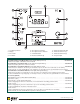
• Measures soil resistivity (4-Point)
method
• Measures ground resistance (2- and
3-Point) Fall-of-Potential method
• Step voltage tests and touch
potential measurements
• Auto-Ranging: automatically selects
the optimum range
• Designed to reject high levels of
noise and interference
• Extremely simple to operate:
connect – press – read
• LED on faceplate informs operator of
high input noise, high auxiliary rod
resistance and fault connections
• Large easy-to-read backlit display
• Battery powered (Model 4620)
• AC powered with rechargeable
NiMH batteries (Model 4630)
• Rugged dustproof and rainproof
field case
• Can also be used for continuity
tests on bonding
• Color-coded terminals
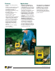
Applications
• Three-Point measurements of
resistance to ground of ground
rods and grids. Three-Point mea-
surements are generally used when
the electrode or grid can be easily
disconnected, if corrosion is
suspected, or in circumstances where
ground faults are unlikely to occur.
• Four-Point tests or soil resistivity
measurements. Locating areas of
lowest soil resistivity is essential for
achieving an economical grounding
installation.
• Touch potential measurements, an
alternative to 3-Point tests in
evaluating electrical safety. This
test is recommended when the ground
cannot be disconnected, where
ground faults are highly likely to
occur, or when the “footprint” of
grounded equipment (the outline of
the part of equipment in contact with
the earth) is comparable to the size
of the ground to be tested.
• Two-Point tests for continuity tests
on bonding or on pre-established
grounds. This test is commonly
performed in urban environments
where proper auxiliary electrode
placement may be obscured by
confined real estate. Measurements
are referenced against a good local
ground conductor.