
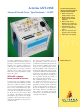
Instruction Manual

Alarm generation, dynamic
Alarm types .................... LOS,LOF,AIS-L, RDI-L, LOP-P,
AIS-P, UNEQ-P, PLM-P, RDI-P, RDIEPP,
RDIEPS, RDIEPC, PDI-P
m alarms in n frames . . ................ m=1ton±1,n
max
= 8000
or
t1 alarm active,
t2 alarm passive .....................t1=0to60s,t2=0to600s
Alarm generation, static (on/off)
Alarm types .................... LOS,LOF,AIS-L, TIM-L, RDI-L,
LOP-P, AIS-P, UNEQ-P, PLM-P, TIM-P,
RDI-P, RDIEPP, RDIEPS, RDIEPC, PDI-P
DS1, DS2 and DS3 output signals
Signal structures
±
Unframed test pattern
±
Framed test pattern (only DS1, DS3)
DS1 frame structure . . ................................ SF,ESF
DS3 frame structure . . . ...........................M13,Cparity
Error insertion
Bit errors in test pattern ....................error rate, single error
BPV............................................. single error
DS1Fbit(LOF).................. single error, 2 in 4, 2 in 5, 2 in 6
CRC-6 (ESF) ............................ single error, error rate
DS3Fbit(LOF)........... single error, 2 in 2, 2 in 3, 3 in 3, 3 in 15,
3in16,3in17
P parity, CP parity, FEBE ................... single error, error rate
Error rate .................................1610
±2
to 2610
±9
Alarm insertion
DS1...................................... LOF,AIS, YELLOW
DS3........................... LOF,AIS, YELLOW, IDLE, FEAC
FEAC Far-End Alarm and Control Signals
To test that FEAC alarm and status information is correctly
transmitted, the relevant signal codes can be selected and inserted into
the DS3 C-bit frame format.
Test patterns
Pseudo-random bit sequences
PRBS: 2
11
±1, 2
15
±1, 2
20
±1, QRSS 20, 2
11
±1 inv., 2
15
±1 inv., 2
20
±1 inv.,
2
23
±1 inv.
Programmable word
Length ..............................................16bits
Receiver unit
Digital inputs
Interfaces to ....... Telcordia GR-253, TR-TSY-000499, ANSI T1.102
75 O coaxial input; adapter jack selectable from Versacon 9 adapter
system
Bit rates and line codes
DS1.............................. 1544 kbit/s; B8ZS, AMI, CMI
DS2................................... 6312 kbit/s; B8ZS, CMI
DS3................................. 44736kbit/s; B3ZS, CMI
STS-1 . ...............................51840kbit/s; B3ZS, CMI
STS-3 . ................................... 155520kbit/s; CMI
100 O balanced input, Bantam jack
Bit rate and line codes
DS1...............................1544 kbit/s; B8ZS, AMI, CMI
Input levels
DS1....................................... DSX-1 compatible
DS3, STS-1 ............................... HIGH,LOW,DSX-3
Clock recovery pulling range .........................
+
500 ppm
Selectable input gain, CMI coded .....................15to23dB
B3ZS, B8ZS, HDB3, AMI coded ......................15to26dB
Selectable adaptive equalizers for DS3, STS-1.................450ft
DS1 .....................1310 ft
Monitor input for STS-3 and STS-12 NRZ signals
See chapter Optical Interfaces for details.
STS-3 receive signal
(for signal structure, see under generator unit)
The ANT-20 demultiplexes one selectable STS-1 tributary from STS-3
and feeds it to the internal processor for evaluation.
STS-1, DS1 and DS3 receive signals
Signal structures as for generator unit
Trigger output
75 O BNC connector, HCMOS signal level
Pulse output for received bit errors, transmit frame trigger, transmit
pattern trigger or 2048 kHz reference clock
Included mapping
VT1.5 and STM-0 mapping
DS1 in STS-1 and 1.5 Mbit/s in STM-0
Modes ................ asynchronous, byte synchronous (floating)
Error insertion and measurement
Additional error types . ........................... BIP-V,REI-V
Alarm generation, dynamic
Alarm types................ LOP-V,AIS-V, LOM, UNEQ-V, RDI-V,
RDIEVP, RDIEVS, RDIEVC, RFI-V, PDI-V, PLM-V
m alarms in n frames . . ................ m=1ton±1,n
max
= 8000
or
t1 alarm active,
t2 alarm passive .....................t1=0to60s,t2=0to600s
Alarm generation, static (on/off) and evaluation
Alarm types .............................. LOP-V,AIS-V, LOM,
UNEQ-V, PLM-V, TIM-V, RDI-V, RDIEVP,
RDIEVS, RDIEVC, RFI-V
Alarm detection only . . ................................ NDF-V
Automatic modes
Autoconfiguration
Automatically sets the ANT-20 to the input signal. The routine searches
at the electrical and optical interfaces for the presence of standard
asynchronous and STS-N/OC-N signals (GR-253, ANSI T1.102) and
the payload contents in channel 1.
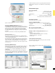
Automatic SCAN function
The SCAN function permits sequential testing of all VT1.5 or
VT2 channels in a SONETsignal. The ANT-20SE receiver checks for
alarms in the receive signal, the SONETstructure and all channels and
for synchronization of the selected test pattern in all channels. The
results (OK/not OK) for each channel are entered in a matrix. The
generator runs simultaneously and can be used to stimulate the device
under test.
4