
Instruction Manual
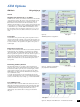

The ATM module comprises:
±
Generation and analysis of ATM cell streams
±
ATM layer cell transfer performance as per ITU-T I.356, O.191
±
AAL-1 segmentation/reassembly for circuit emulation
±
STS-3c/STM-1 with C4 ATM mapping, ANSI T1.105/107,
ITU-T G.707
±
F4/F5 fault management OAM flow for AIS and RDI as per
ITU-T I.610, ATM forum UNI 3.1
Generator unit
Bit rates of the framed cell streams ................. 155.520 Mbit/s
Cell scrambler X
43
+1 (ITU-T) ........... canbeswitched on and off
Test cell channel
Adjustable from ............................ 0to149.760 Mbit/s
Header setting ........................................ editor
Load setting in ............................. Mbit/s, Cells/sec, %
Test cells, payload pattern
AAL-0, Pseudo-Random
Bit Sequences (PRBS) . .......................2
11
±1, 2
15
±1, 2
23
±1
AAL-1, Pseudo-Random
Bit Sequences (PRBS) . .......................2
11
±1, 2
15
±1, 2
23
±1
Programmable word, length .............................16bits
Test pattern for ATM performance analysis, with
Sequence number ..................................... 3bytes
Time stamp ......................................... 4bytes
Error correction ......................................CRC-16
Load profiles
Equidistant, setting range ................... 1to10000celltimes
Constant Bit Rate (CBR), setting range . ........... 0.01% to 100 %
Variable Bit Rate (VBR), settings
Peak cell rate ................................... 1%to100%
Mean cell rate .................................. 1%to100%
Burst size................................ 1to1023 cell times
Burst period ............................ 2to32767celltimes
Error insertion
Physical layer as with ANT-20SE basic instrument ATM layer, AAL:
Correctable and non-correctable header errors
±
AAL-0, cell payload bit errors
±
AAL-1, sequence number errors
±
AAL-1, SAR-PDU bit errors
±
AAL-1 SNP, CRC errors
±
AAL-1 SNP, parity errors
Triggering ............................. single errors, error ratio,
n errors in m cells
Alarm generation
Physical layer as with basic instrument, also:
Loss of Cell Delineation ................................. LCD
ATM layer (for selected test cell channel):
OAM F4/F5 fault flow . ...........VPAIS, VP RDI, VP AIS+VC AIS,
VC AIS, VC RDI, VP RDI+VC RDI
Background load generator
For programming user-defined cell sequences. The sequences can be
transmitted at a selectable repetition rate.
Editor . .................................... 200ATMchannels
Header ....................................... user-selectable
Payload ............................. 1filler byte, user-selectable
Circuit emulation
(for selected test cell channel)
Generation of
an asynchronous channel....................... 1544, 2048, 6312,
8448, 34 368, 44 736 kbit/s,
2048 kbit/s with PCM30 frame structure
ATM channel segmentation ...................AAL-1, ITU-T I.363
Receiver unit
Bit rates of framed cell streams .................... 155.520 Mbit/s
Cell scrambler X
43
+1 (ITU-T) ........... canbeswitched on and off
Measurement types
Error measurement (anomalies), statistics
Detection of the following error types:
Correctable and non-correctable header errors
±
AAL-0, cell payload bit errors
±
AAL-1, sequence number errors
±
AAL-1, SAR-PDU bit errors
±
AAL-1 SNP, CRC errors
±
AAL-1 SNP, parity errors
ATM performance analysis
±
Cell error ratio
±
Cell loss ratio
±
Cell misinsertion rate
±
Mean cell transfer delay
±
2-point cell delay variation
measured between minimum and maximum cell transfer delay
values
±
Cell transfer delay histogram
Number of classes . . . . . . . . . . . . . . . . . . . . . . . . . . . . . . . . . . 128
Minimum class width . . . . . . . . . . . . . . . . . . . . . . . . . . . . . 160 ns
Maximum class width . . . . . . . . . . . . . . . . . . . . . . . . . . . . 335 ms
Settable offset . . . . . . . . . . . . . . . . . . . . . . . . . . . . . . . 0 to 167 ms
Offset step width. . . . . . . . . . . . . . . . . . . . . . . . . . . . . . . . . 2.5 ms
Alarm detection (defects)
Physical layer as with ANT-20SE basic instrument, also:
Loss of cell delineation . .................................. LCD
ATM layer (for selected test cell channel):
OAM F4/F5 fault flow . ...........VPAIS, VP RDI, VC AIS, VC RDI
User channel analysis
Concurrent X-Y chart (load vs. time) for:
±
All user cells
±
Average cell rate of a selected cell channel
±
Peak cell rate of a selected cell channel
Display units .............................. Mbit/s, Cells/sec, %
Channel utilization histogram
±
All user cells (ªassigned cellsº)
±
A selected cell channel (ªuser cellsº)
Cell distribution of a selected cell channel with classification by:
±
User cells
±
F5 OAM flow
±
F4 OAM flow
±
User cells with CLP = 1
Circuit reassembly
(for selected test cell channel)
Reassembly ................................ AAL-1, ITU-T I.363
Error measurement on an
asynchronous channel . ................... 1544, 2048, 6312, 8448,
34 368, 44 736 kbit/s,
2048 kbit/s with PCM30 frame structure
20