
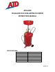
User's Manual
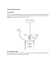


WARNING:MAXPressure–7psi.Neverpressurizetankwithballvalveopen.
Ifusedoildoesnotevacuat etankuponpressurization,checkthatballvalveisfullyclosed(handle
in horiz on tal position). If this does not correct the problem, remove the unit from service and
contactanauthorizedservicecenterfor
repair.
If the pop‐off valve relieves ANY air pressure from the tank, remove the unit from ser vice and
contactanauthorizedservicecenterforrepair.
WARNING:
ALWAYSremoveoildrainandanytools,jacks,etc.andfromundervehiclebeforeloweringlift.
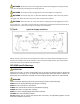
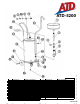
ASSEMBLY
1. Removetankfrombox.Slide1/2 ” diametersteelaxle(#25)throughaxlehousingonbottomof
tank (#15). Place wheel (#21) on axle (#25), securing with washer and retaining ring (#22 &
#23).Repeatforotherwheel.
2. Remove wood spacers from casters brackets. Slide stud of caster (#20)
through bracket,
securingwithwasherandnut(#18).Repeatforothercaster.
3. PlaceTFEpipesealantonthreadof3/4 ” NPTbarbedfitting(#1 7)andscrewintolowerfittingon
sideoftank(#15).Slideloopclamp(#16)overendofhose(#14).Thenpushendofhose
(#14)
over barbedfitting(#17).Slidetheloopclamp(#16) down overhose (#14) andbarbedfitting
(#17)andtightenforuse.
4. Placeloopclamp(#13)aroundtubingandfastentotank(#15).Continuallykeepingtensionon
hosetokeepasstraightaspossible.
5. PlaceTFEpipesealant
on 1‐1/2 ” NPTnipple(#5)ontop dome of tank. Screw1‐1/2 ” ball valve
(#7)in totank(#15).Screwclampingknob(#4)into 4”pipenipple(#3).(NOTE:Onlyoneofthe
fourholesin4”nippleisthreade d.Theother3holesarenon‐threadedpressurereliefports.)
6. PlaceTFEpipesealantonfunnelassembly(#1).Thenputdraintube(#2)andfunnelassembly
(#1)intotank(#15)throughthe 4”nipple(#3)and ballvalve(#7)assembly.Allfittingsshould
betightsoastopreventanyleaking.