
Manual


8
SCM20ASL/20PSL Pro
9. Specifications
SCM20ASL Pro
1. Acoustic
l Drive unit - Low Frequency (LF) 6.5”/150mm Super Linear with 75mm/3" voice coil (SB75-150SL 8 Ohm)
l Drive unit - High Frequency (HF) 1”/25mm dual suspension Soft Dome (SH25-76S 6 Ohm)
l Amplitude linearity 80Hz - 20kHz (+/-2dB)
l Cut-off frequencies 55Hz - 25kHz (-6dB freestanding)
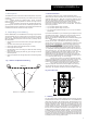
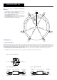
l Horizontal dispersion +/-80° coherent
l Vertical dispersion +/-10° coherent
l Maximum continuous SPL 108dB (per pair @ 1m)
l Crossover frequency 2.1kHz
2. Electronic
l Audio input Rear panel mounted female XLR (pin 2 +ve)
l Input sensitivity 1V/2V RMS or +2.2/+8.2dBu via switch (ref. bass full output)
l Input sensitivity trim 0dB to -6dB (via rear panel pot)
l Total input sensitivity range 1V/+2.2dBu to 4V/+14.2dBu
l Input impedance 10kΩ per leg
l LF amp max output power 200W continuous (1% THD)
l HF amp max output power 50W continuous (1% THD)
l THD LF amp 0.0006%/-104.4dB (100Hz, 1dB below rated power)
l THD HF amp 0.0022%/-93.2dB (10kHz, 1dB below rated power)
l Crossover filters 2nd order/ 12dB/oct critically damped with phase compensation
l HF upper -3dB point 250kHz
l S+N/N ratio - LF 112dBA (Max. gain, ref. 40V out, IEC ‘A’)
l S+N/N ratio - HF 109dBA (Max. gain, ref. 20V out, IEC ‘A’)
l Low frequency shelf cut/boost 80Hz, -2dB to +3dB in 1dB steps (via rear panel rotary switch)
l Overload protection Active FET momentary gain reduction (inc. front panel mounted ‘limit’ LED)
Amplifier thermal trip circuit
l Mains power requirements 115/230V, 50/60Hz (internally selectable by technician). 100V 50/60Hz factory set.
l Max power consumption 381Watts/483VA
l Accessories K&M 24120 Wall Mount (cabinet requires modification to accept ‘top-hat’ mount)
l Weight 28kg/61.6lbs (per cabinet)
SCM20PSL Pro
l Drive unit - Low Frequency (LF) 6.5”/150mm Super Linear with 75mm/3" voice coil (SB75-150SL 8 Ohm)
l Drive unit - High Frequency (HF) 1”/25mm dual suspension Soft Dome (SH25-76S 6 Ohm)
l Amplitude linearity 80Hz - 20kHz (+/-2dB)
l Cut-off frequencies 55Hz - 25kHz (-6dB freestanding)
l Horizontal dispersion +/-80° coherent
l Vertical dispersion +/-10° coherent
l Maximum continuous SPL 108dB (per pair @ 1m)
l Crossover frequency 2.1kHz
l Recommended Power Amplifier 75 to 300 Watts
l Nominal Impedance 8 Ohm
l Connectors 2 x Pairs Binding Posts/4mm Plugs - Bi-Wireable
l Accessories K&M 24120 Wall Mount (cabinet requires modification to accept ‘top-hat’ mount)
l Cabinet Dimensions (HxWxD) 450x250x294mm
l Weight 18kg/39.7lbs (per cabinet)
Specifications comply with the following standards:Australian Standard Specification No 1127 "Sound System Loudspeakers" Part 5, IEFE Specification Standard No 219-1975
Acoustic Transducer Co. is a trading name and ATC is the registered trade mark of Loudspeaker Technology Ltd.
E. & O.E. The policy of ATC is that of continuous design and development. ATC reserves the right to alter products and specifications without prior notice.
SCM20ASL/20PSL Pro
6
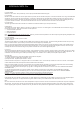
6.3 Power Switch
Switches on the monitor. When powered up, the front panel power/limit LED will illuminate green.
6.4 Fuseholder
Should a monitor fail to switch on when the power switch is operated, the fuse should be inspected. Lift out the fuseholder cover using a small flat-blade
screwdriver, remove the fuse and inspect for damage. If required, a replacement fuse should be fitted. Ratings are printed on the amp rear panel. It
should be stressed, however, that fuses most often fail only because of a serious electrical fault. If this is the case then simply replacing the fuse will
only result in another fuse failure. The monitor should be returned to ATC or an authorised service technician if a second fuse fails.
6.5 Input Socket
The audio signal cable should be connected here. Balanced or unbalanced cables may be used (see Section 3.).
6.6 Bass Shelf
This adjustment provides -2dB to +3dB of cut and boost, in 1dB steps, in the form of a shelving filter. This subtracts/adds more warmth and energy in
the low frequency region. When used to boost it is at the expense of:
Ÿ Accurate transient reproduction
Ÿ Reduced Headroom
Ÿ Increased distortion
Note: This adjustment should be used for fine tuning. Please try to achieve the best possible in-room bass response by first adjusting loudspeaker and
listening position and room acoustic treatment if possible.
6.7 Input Sensitivity
This user adjustment is made up of two controls:
a) Selector Switch
This switch toggles between 1V/+2.2dBu and 2V/+8.2dBu input sensitivity (for full amp output). Choose the setting that best suits the source pre-amp,
mixer or monitor controller. Input sensitivity can be further fine-tuned using the Input Sensitivity Trim.
Note: For source (driving) equipment with potentiometer based analogue level control, choose an input sensitivity that results in the desired average
sound pressure level with the source level control at approximately 50%. For source (driving) equipment with a digital level control, choose an input
sensitivity that results in the desired average sound pressure level with the level control at approximately 80%.
b) Trim Pot
This control provides fine adjustment of input sensitivity. Fully clockwise is the factory ‘reference’ position of 0dB. In this position, the trim has no affect
on the input sensitivity which is controlled by the switch described above. Turning the control anti-clockwise will result in up to -6dB of adjustment. The
combination of the two controls gives a total input sensitivity range of 1V/+2.2dBu to 4V/+14.2dBu (for full amplifier output of 200W).
6.7 Fault LED
This LED will illuminate if one of two fault conditions occurs within the amplifier:
1) Thermal Overload - amplifier plate temperature > 60°C
2) Output DC offset - amplifier output DC offset > 100mV
If thermal overload is suspected - an amp plate of 60°C is uncomfortable to touch - turn off the amp and leave it to cool for 15 minutes. If the amplifier
re-starts without the fault LED, the temperature will have fallen and the fault cleared.
However, thermal overload is not typical. The heat sinking on the amplifier has been specified to control the amp temperature under normal working
conditions. If the amplifier plate has reached 60°C, then it is very likely one of the following conditions applies:
1) The monitor is being driven continuously at very high SPL or with signals that are continuous in nature ie. sine waves - REDUCE THE SOUND
PRESSURE LEVEL
2) The heat sink and amp plate are covered or partially covered, blocking or reducing the cooling airflow - DO NOT RESTRICT COOLING
3) Ambient temperature in the control/listening room or in the area in close proximity to the monitor is in excess of 33°C - REDUCE AMBIENT
TEMPERATURE
Failure to correct any of the above is likely to result in excessive amp heating and repeated thermal trips.
Condition 1. is likely to cause premature drive unit failure and accelerated amplifier component ageing.
Conditions 2. & 3. are likely to cause accelerated amplifier component ageing.
If the amplifier will not re-start after a cooling period, it is highly likely there is a fault leading to a DC voltage in excess of 4.0V on the amplifier outputs.
This will require repair by ATC or a approved service engineer. Please contact your local ATC dealer or ATC direct if this is the case.
Note:
Due to the nature of the electronics in ATC active loudspeakers it is quite normal for a sound to be heard from the speaker when the power is applied or
disconnected. The noise heard, and the movement observed in the bass drive unit will not damage the speaker, and is quite normal. Although ATC
uses the highest-grade components, a different noise may be heard from each speaker due to slight tolerance variations in the amplifier components.