
Installation Instructions


Installatievoorschrift ATAG E-Serie
21
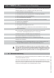
6.10.1 Dimensionering afvoerkanaal / toevoerkanaal
De diameter wordt bepaald door de totale lengte, inclusief aansluitpijp, en het verloop
van het rookkanaal (zoals bij inmeten is vastgesteld) en het type ketel. Een te kleine dia-
meter kan leiden tot storing. Zie tabel 6.10.1.a voor keuze van het systeem met de juiste
diameter. De tabel toont de maximale afvoerlengte bij verschillende ketelvermogens.
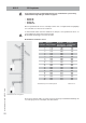
Toelichting op tabel 6.10.1.a:
Tweepijps afvoersysteem: maximale opgegeven lengte = afstand tussen
ketel en dakdoorvoer A.
Concentrisch afvoersysteem: maximale opgegeven lengte = afstand tussen
ketel en dakdoorvoer B.
Bij toepassing van bochten moet de opgegeven waarde achter elke bocht van de maxi-
male rechte lengte afgetrokken worden (zie voorbeeld).
De diameter 60/100 mag uitsluitend toegepast worden op geveldoorvoeren in
combinatie met de ATAG E223C.
ø80mm
A
in m
E223C Maximale rechte lengte 80 35,5
weerstandslengte 87° bocht -1,5
weerstandslengte 45° boch
t
-0,8
E264C Maximale rechte lengte 80 18
E325C weerstandslengte 87° bocht -1,5
E325EC weerstandslengte 45° boch
t
-0,8
E320S
ø60/100mm
B
in m
ø80/125mm
B
in m
E223C Maximale rechte lengte 60/100 6 Maximale rechte lengte 80/125 30
weerstandslengte 87° bocht -1,6 weerstandslengte 87° bocht -2,8
weerstandslengte 45° boch
t
-1 weerstandslengte 45° boch
t
-1,1
E264C Maximale rechte lengte 80/125 13
E325C weerstandslengte 87° bocht -2,8
E325EC weerstandslengte 45° boch
t
-1,1
E320S
ø45mm
C
in m
Schoorsteencorrectiefacto
r
zie hoofdstuk 'Instellingen'
Para
683
E223C Maximale rechte lengte 45 15 Correctiefactor bij 15 mtr 14
weerstandslengte 87° bocht -1,6 Correctiefactor bij 10 mtr 0
weerstandslengte 45° bocht -1 Correctiefactor bij 5 mtr 0
weerstandslengte dakdoorvoe
r
-2 Correctiefactor bij 0 mt
r
0
E264C Maximale rechte lengte 45 15 Correctiefactor bij 15 mtr 30
E325C weerstandslengte 87° bocht -1,6 Correctiefactor bij 10 mtr 25
E325EC weerstandslengte 45° bocht -1 Correctiefactor bij 5 mtr 12
E320S weerstandslengte dakdoorvoe
r
-2 Correctiefactor bij 0 mt
r
0
ø60mm
C
in m
Schoorsteencorrectiefacto
r
zie hoofdstuk 'Instellingen'
Para
683
E223C Maximale rechte lengte 60 14 Correctiefactor bij 14 mtr 5
weerstandslengte 87° bocht -1,6 Correctiefactor bij 10 mtr 4
weerstandslengte 45° bocht -1 Correctiefactor bij 5 mtr 1
weerstandslengte dakdoorvoe
r
-2 Correctiefactor bij 0 mt
r
0
E264C Maximale rechte lengte 60 15 Correctiefactor bij 15 mtr 20
E325C weerstandslengte 87° bocht -1,6 Correctiefactor bij 10 mtr 17
E325EC weerstandslengte 45° bocht -1 Correctiefactor bij 5 mtr 11
E320S weerstandslengte dakdoorvoe
r
-2 Correctiefactor bij 0 mt
r
0
Concentrisch afvoersysteem
Tweepijps afvoersysteem + Schoorsteenvoeringen
Miniflex 60mm
Miniflex 45mm
Dimensionering rookgasafvoer / luchttoevoer Tabel 6.10.1.a
Voorbeeld:
Een E223C met een con-
centrisch afvoersysteem
ø80/125mm heeft volgens de
tabel een maximale rechte af-
voerlengte van 30m.
In het toe te passen systeem
moeten 2x een 45° bocht op-
genomen worden.
De maximale afvoerlengte
wordt dan:
30 - 2x1,1 = 27,8m.
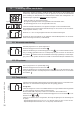
Bij toepassen van mi-
nifl ex moet een aan-
passing uitgevoerd
worden op het maxi-
mum toerental van de
ventilator. Deze is via
parameter 683 volgens
bovenstaande tabel in
te stellen.
Vul de correctie in op
de desbetreffende stic-
ker bij de typeplaat op
het toestel.