
User`s manual
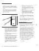
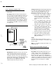
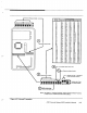

Mount/Install: Refer to Figure A-2. Before you
mount the CCU, consider the Appendix informa-
tion concerning the choice of location for wireless
devices.
e-e-
9
5
I
Figure A-2 Wireless Module
\
J
NOTE:
It is much easier to set the housecode (transmitter
settings must match this wireless module’s
settings) before mounting the module.
1.
2.
3.
4.
5.
6.
7.
Set the DIP switches to the housecode
(see below). If you are planning on using
the Remote Antenna Coupling Unit (Model
8326)
set the power jumper to ON now.
Install the antenna on the module.
Knock out the CCU antenna hole.
Install the grommet in the antenna hole.
Slide the antenna up through the antenna
hole and mount the module on the studs.
The base of the antenna should fit into the
grommet so that the entire antenna
extends from the CCU enclosure.
Tighten the nuts holding the module.
Use the self-tapping screw to mount the 5-
Foot Counterpoise on the outside of the
lower left corner of the enclosure.
NOTE:
This counterpoise wire is a necessary balance for
the wireless system’s antenna. Do not cut, coil, or
bend the wire back upon itself; however, any
reasonably straight configuration will be accept-
able (for instance, you could run the Counterpoise
down a wall, turn and run the rest horizontally
along a baseboard).
Avoid having the Counterpoise next to other
wires, pipes, or metal, since that would hurt
reception.
The Counterpoise is not required if the Remote
Antenna Coupling Unit (Model 8326) is used.
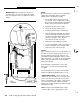
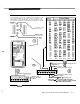
Settings/Connections:
Set the module’s dip
switches for the selected house code; this same
house code must be set into all of the system’s
wireless transmitters’ dip switches. After mount-
ing, connect the module’s cable to the Main
board in the location shown in the figure; the plug
will fit only one way.
Data: Frequency: 40.68 MHz Power require-
ments:12 VDC, 20 ma, supplied by the CCU.
,’
(
_.
L
A-4
AT&T Security System 8300 Installer’s Manual